Week 8 - Challenge 3 - Switch Bezel Design
AIM
- To create the Switch Bezel Plastic component through the given Class-A surface. To begin with, the tooling axis for the given Class-A Surface should be created meeting the requirements of the draft angle and at the end perform the Draft analysis on the model.
- To create plastic component with 2.5 thickness.
Tooling Axis
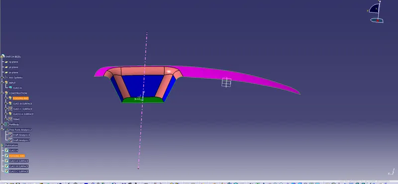
Tooling Axis is creted by Bisecting line between X and Y Direction Tooling axis,first we have to take X direction tooling axis from the XZ plane face with using the interset tool and in the Y direction tooling axis create line by using sketch option.
Draft Analysis
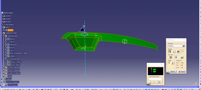
Analysing draft angle with respect to the tooling axis in order to the angle 3 degree.
Class A Surface
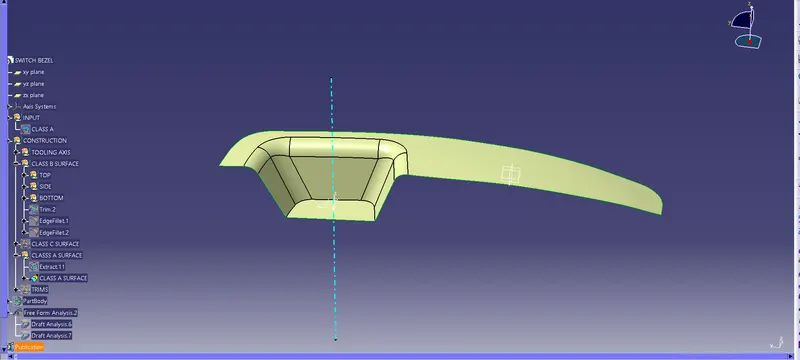
From the Given A Surface, extractef the the suface using tool of extract with point continuity.
Class B Surface.
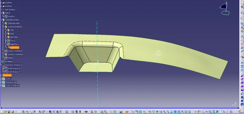
Extracted all flat surfaces and untrimmed, extrapolated and trimmed with each surfaces. after thr trimmed the surfaces offsetted with 2.5 mm thickness from the A Surfaces.
Class C Surfaces.
Creating C Surfaces, from the Boudaries of A surfaces and sweep in the 3 degree angle and trimmed with two boundaries.
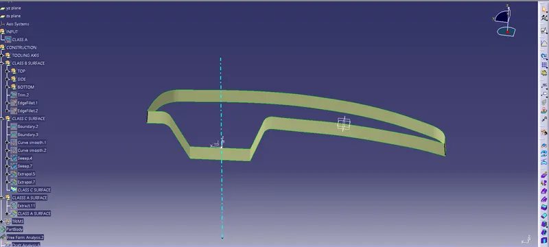
Draft Analysis.
Generating the part body, analysed the Draft angle with respect to the tooling axis which we done like in Class A surface,it shown Green color the angle is positive degree and if shows error like blue color,the angle is negative.
I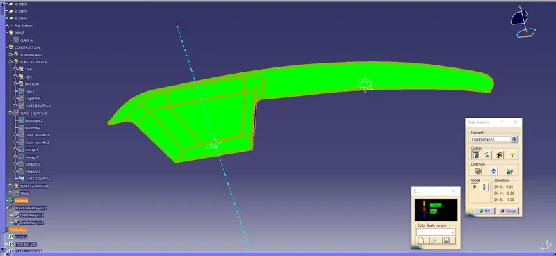
Part Design
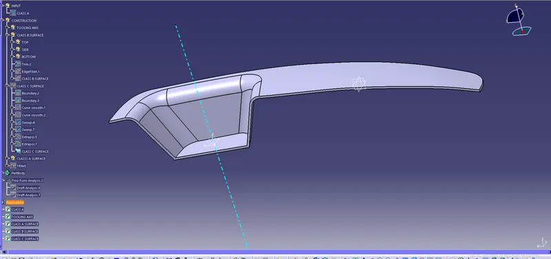
Created the part design with using tool close surface, from changed the workbench surface to part design
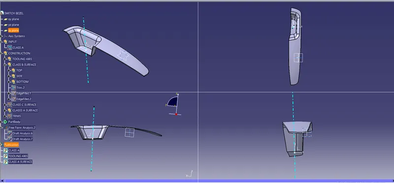
Isometric and Orthgrapic view of Switch bezel
Conclusion,
Finally,we ctreated the plastic component of Switch Bezel through the given Class A Surface with help of Tooling axis creation.Analysed the draft angle for given Class A Surface and Part Design model.