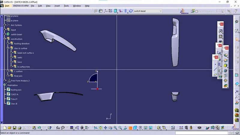
Week 8 - Challenge 3 - Switch Bezel Design
Aim:
- Create the Switch Bezel Plastic component through the given Class-A surface.
Objectives:
- To create a tooling axis for draft analysis on both Class A surface & final body.
- To generate Class B & Class C surface.
- To create solid body from all joined surface.
Design output:
A final body with close surface and publication of tooling axis, Class A surface, Class B & C surface.
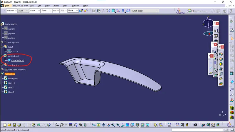
Procedure:
Creation of tooling axis:
- local point on base surface is defined for creation of local axis system to create tooling axis.
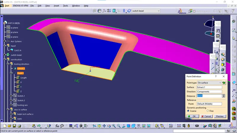
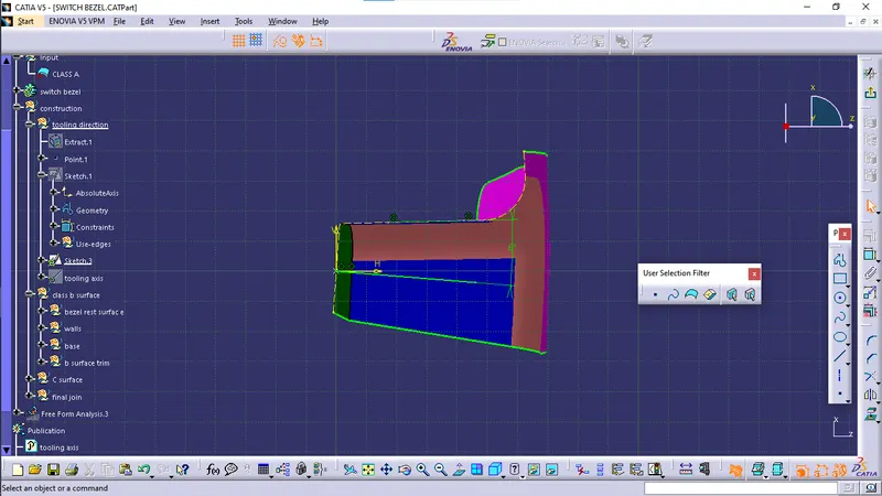
- first bisecting line is created by intersection of two walls on left and right side of switch bezel when viewed from front by local axis system.
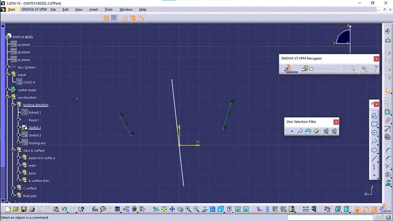
- Second line for proper draft of 2nd wall seen from front is made with 6 degree angle with the intersection as shown below:
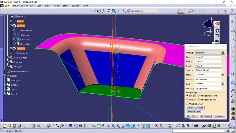
- lines obtained from sketch 1 and sketch 3 is bisected using line command from reference element.
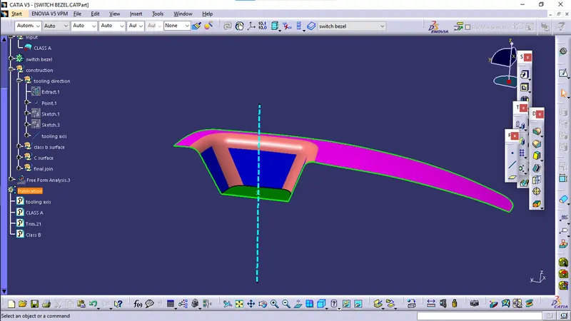
- finally tooling axis is obtained
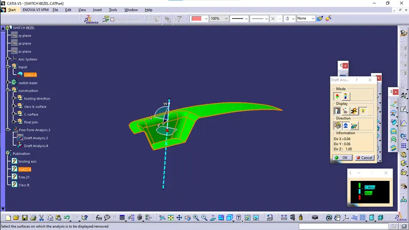
Draft analysis on Class A:
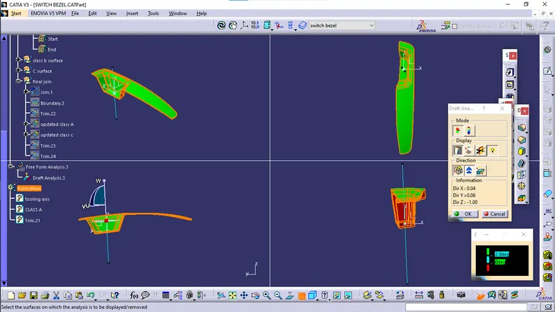
Draft analysis is performed using feature draft analysis tool
Creation of Class B surface:
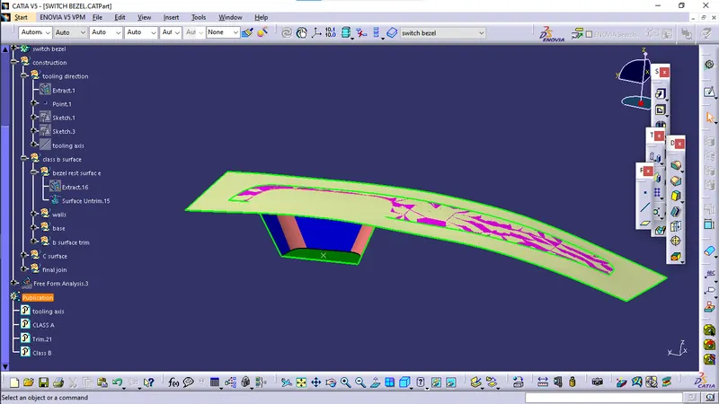
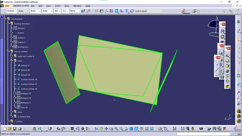
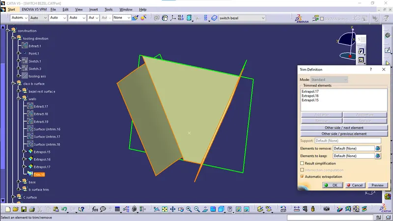
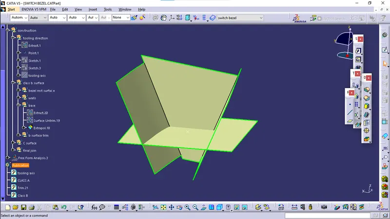
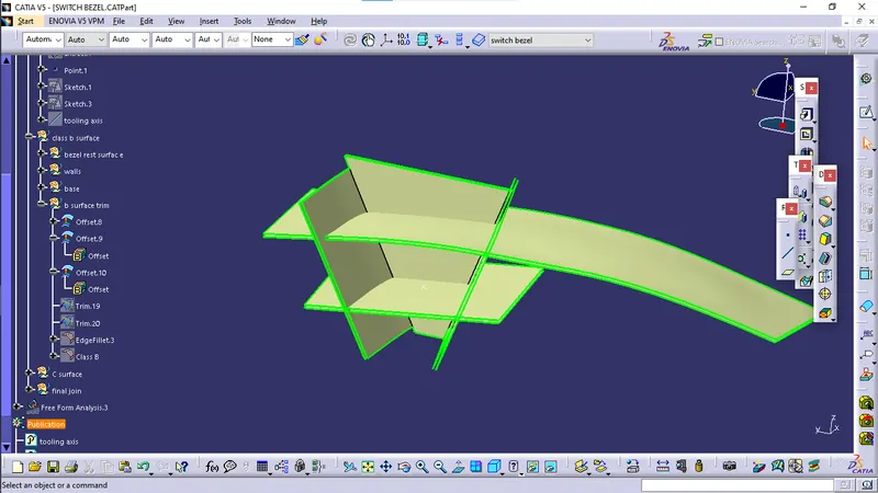
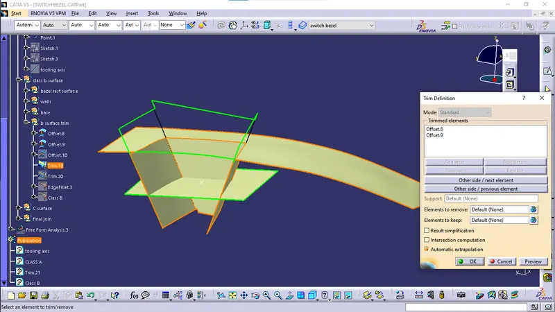
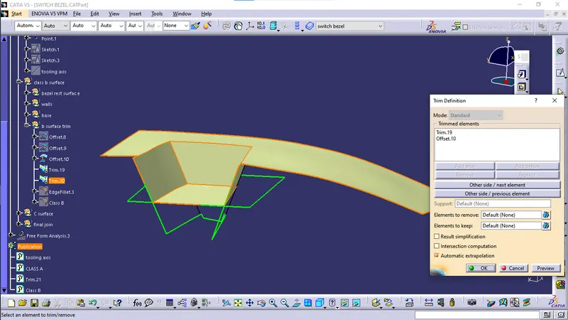
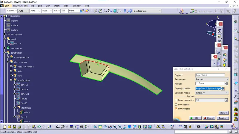
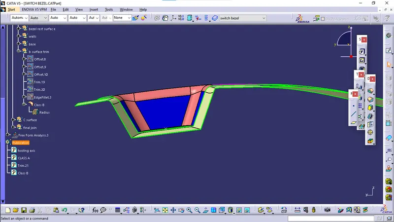
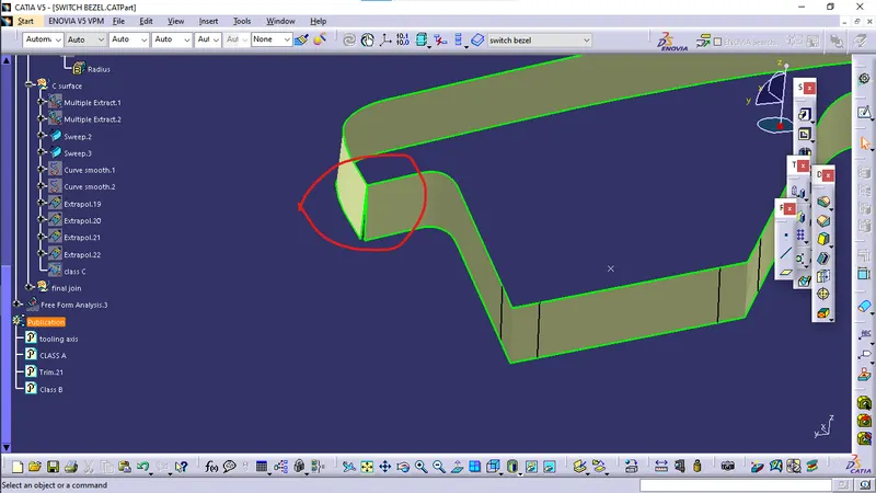
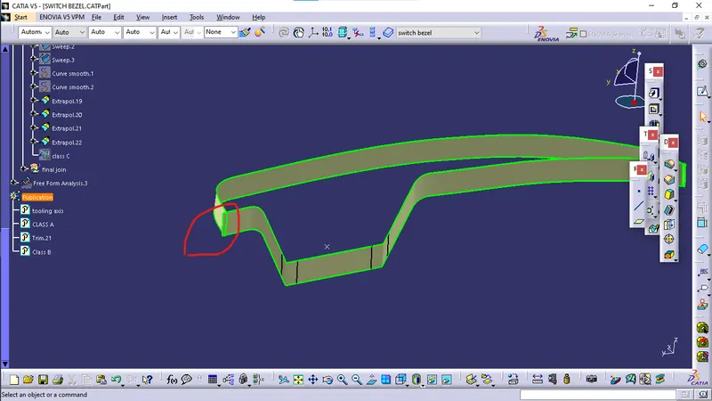
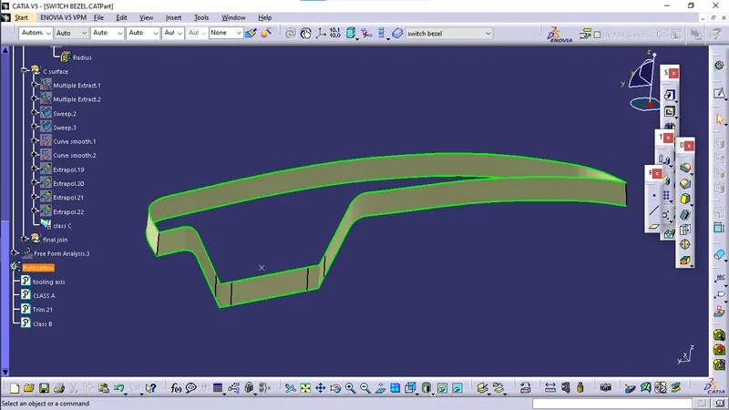
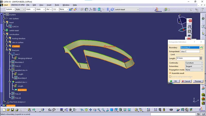
Creation of Class C surface:
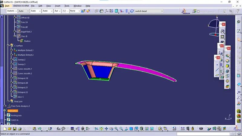
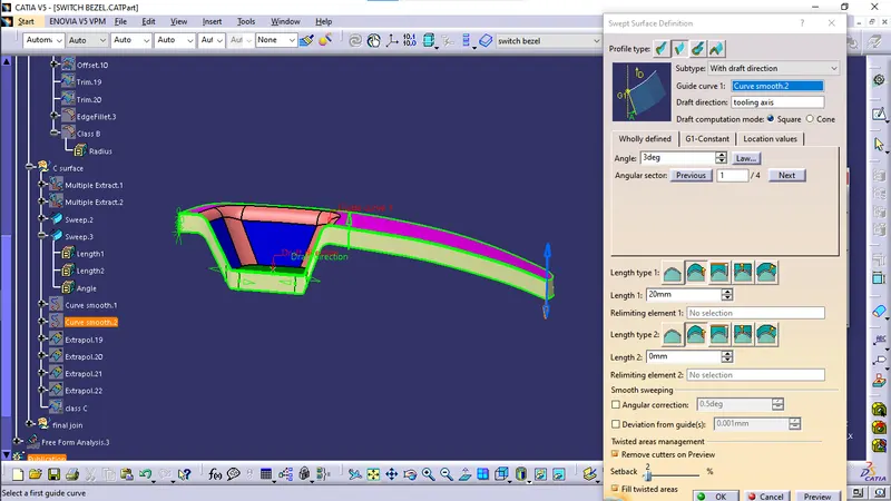
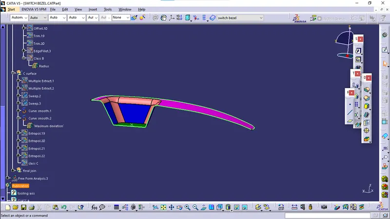
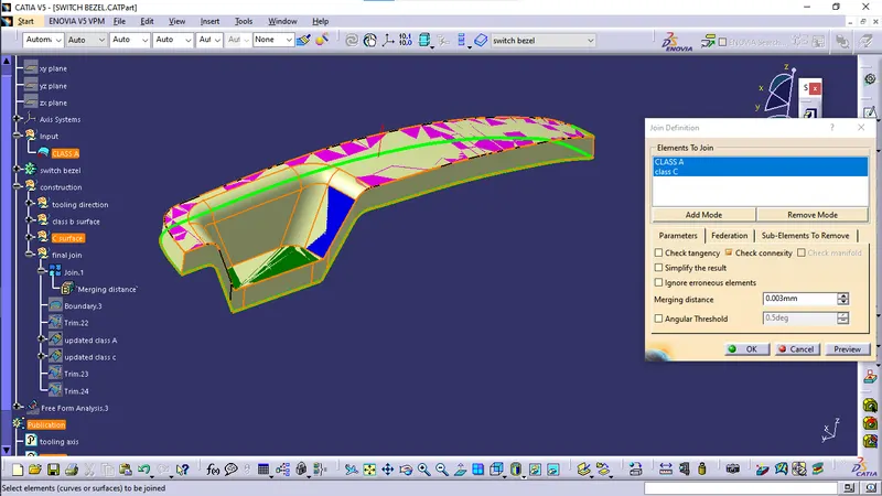
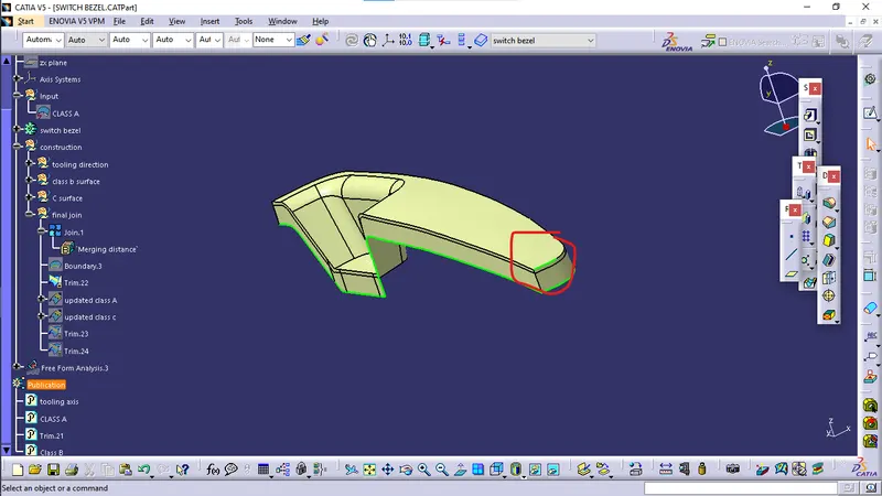
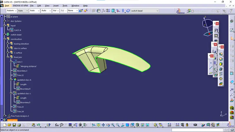
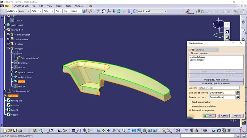
Join Class A, Class B & Class C:
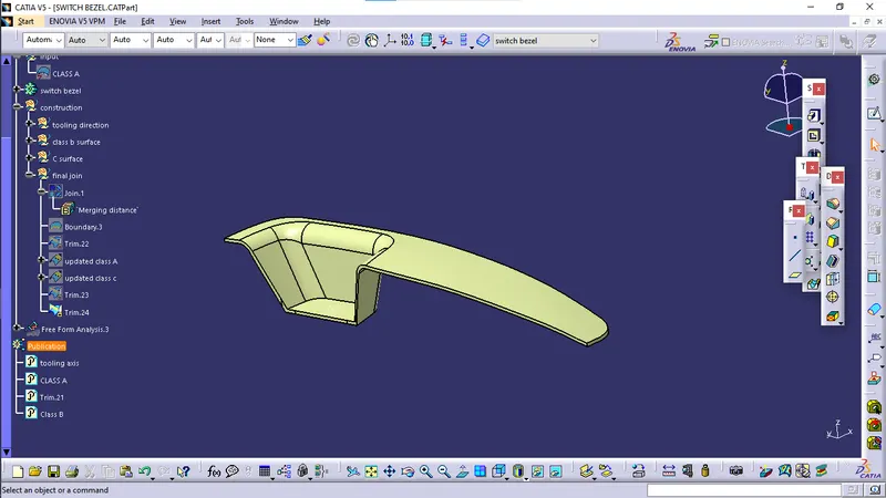
Draft analysis on solid body:
Final Solid body: