Week 8 - Challenge 3 - Switch Bezel Design
OBJECTIVE:
- To carry draft analysis by creating the tooling direction for the given class-A-Surface.
- To create Class B and Class C surface for the given SWITCH BEZEL with the given Class A Surface to design a component
Draft Analysis on a SWITCH BEZEL:
THEORIES OF DRAFT ANALYSIS:
- Draft is required on all parts in the direction of mold movement in order to allow parts ti release or eject from the mold properly.
- Draft is the angle in which the part is tapered to allow it to realese. As the part cools, it tends to want to shrink to the core side of the mold.
- Adding draft helps the part to release. Most parts or application require a minimum of 1/2 to 1 degree, however 3 degrees is widely accepted as the norm.
Draft:
- Draft analysis command which is used to detect the drafted part will be easily removable or not. This type of analysis is perfomed based on the colour variations.
- Tooling direction is the main tool considerations for plasctic part and for all mould parts. Because it defines the mould part to be manufacturable or not and the possibility of the plastic part coming out from the Core and Cavity part.
Draft Analysis Report:
Steps to follow or Approach for the Analysis:
Draft allows the part to release from the mould.
Draft angle is required for all the parts because of the mold movement in order to allow parts to release from mold properly.
CLASS-A-SURFACE:
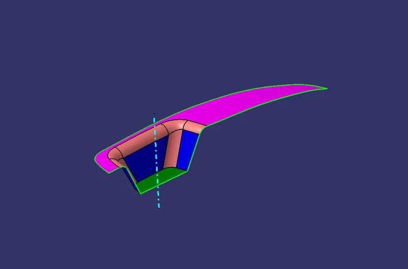
PROCEDURE:
Analyze the part manually to choose which direction is suitable for tooling axis. Whether it is toolable part or not.
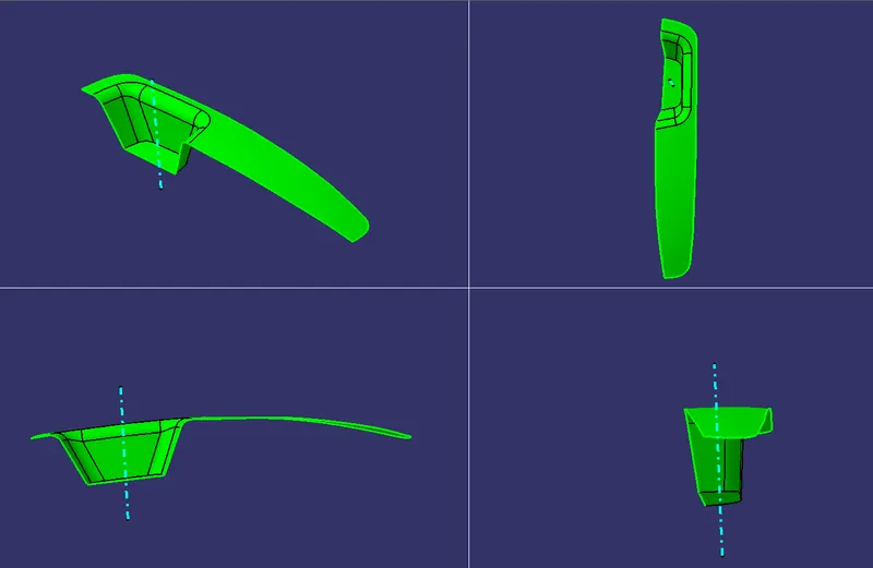
1. From the below image can clearly see the hole which will be used for tooling axis. Because in this model X direction and Y direction are not possible to for put an tooling hole. So, We choose Z direction.
2. From X direction, it will be difficult for tooling the hole and Similarly from the Y direction the hole cannot be seen. So We finalize the decision that the Z direction is the only way for tooling hole for this model.
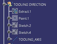
Fig : Structure Tree for Tooling Axis
- Make an axis over the point created with the same direction as the main axis system.
- Create a sketch and choose the intersection command
- choose bisecting options in Line command and bisect those lines over the axis point we selected at first.
Procedure for Draft Analysis of class A surface:
- For the plastic parts, the nominal angle value for draft analysis is 3 degree but even a 0.5 drgree angle can be created for sub-assemblies like ribs and slots.
- Insert - Analysis - Feature Draft Analysis.
- Draft analysis is carried out by pulling the BCS compass to the tooling axis and an inverse draft axis was carried out if needed.
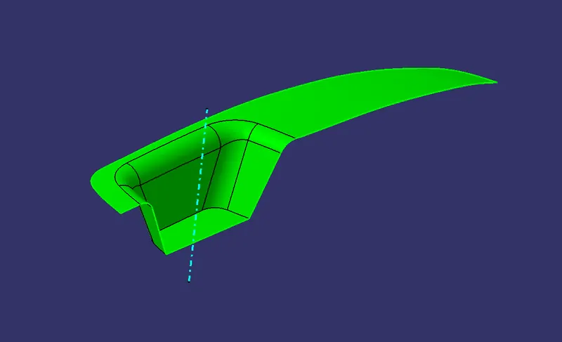
- If the surface gets green then the model passes or else further operations need to be carried out.
Class-A-Surface:
It is the outermost surface of the automobile which gives aesthetic look to the vehicle. It is obtained from clay modelling by reverse engineering.
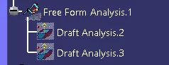
Fig : Structure Tree for Draft Analysis
Now, the draft analysis have to be perform for the above model. Whether to identify all the surface are clearing the minimum draft angle.
Click on the compass icon and align it with the tooling axis and click on the surface, we will get our results. From the above Component we have different kind of angles and Our Tooling Axis Clears all the Mininum requirement to make that component.
Procedure for Creating Class B Surface:
From the Class A surface , Extracted a set of Surface for to create the Class B surface by Using Extract Command From Below Image.
We can use extract command for all surface we needed for to create Class B Surface and then Use the Untrim command to restore the surface up to the limit.
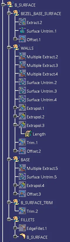
After the Untrim, use the Extrapolate command to Extend the edge upto 10mm.
and then Finally use the trim command to cut the surfaces to get the desired output which we wanted.
Offset the Trimmed Surface up to 2.5mm for the thickness we needed.
Similarly, do the same procedure for all the remaining surface, need to get. we can clearly see in the Structure Tree.
Now, Trim all the parts to get CLASS-B-SURFACE.
Give fillets for all the requied edges. For the fillets add the thickness value, for example if the thickness is 5mm and the radius is 3mm, For Inward add the thickness value with radius and for the outward subtract the thickness value with radius to create a uniform thickness all around the shape.
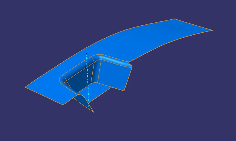
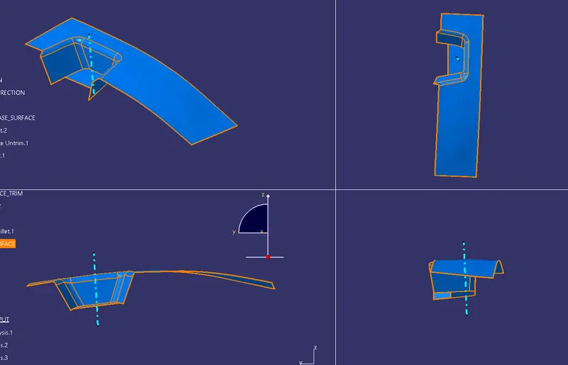
Fig : CLASS B SURFACE
PROCEDURE FOR CREATING CLASS C SURFACE:
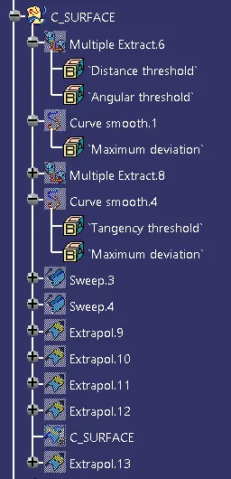
FIG : STRUCTURE TREE FOR CLASS C SURFACE
Use the boundary command to extract the edges from the Class A Surface. Similarly create boundaries for holes too.
Use the Sweep command to get the Class C surface and this is the surface that joins Class A & Class B Surface.
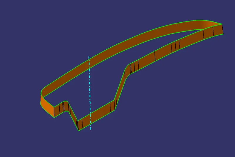
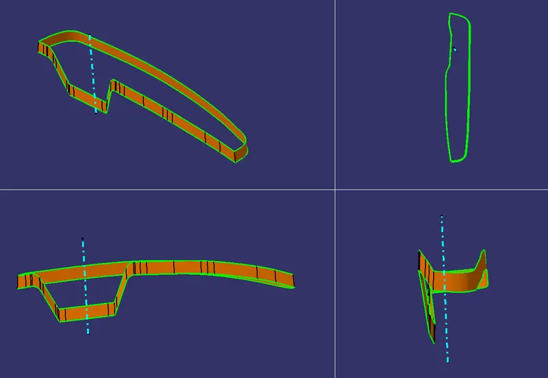
Fig : CLASS C SURFACE
- Joining Class A & C Surface
After joining the Class A & C, Trimming the class AB & C Surfaces and get the final trimmed Switch Bezel closed surface.
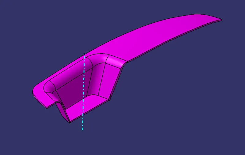
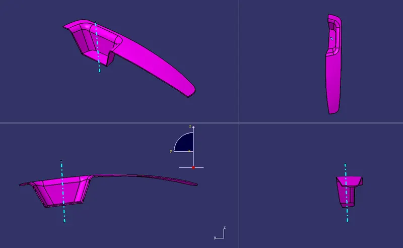
Now go to the Part workbench. Use Closed surface Command to create a solid model and It has been created..
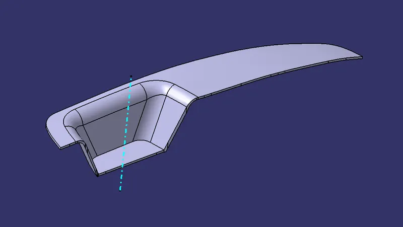
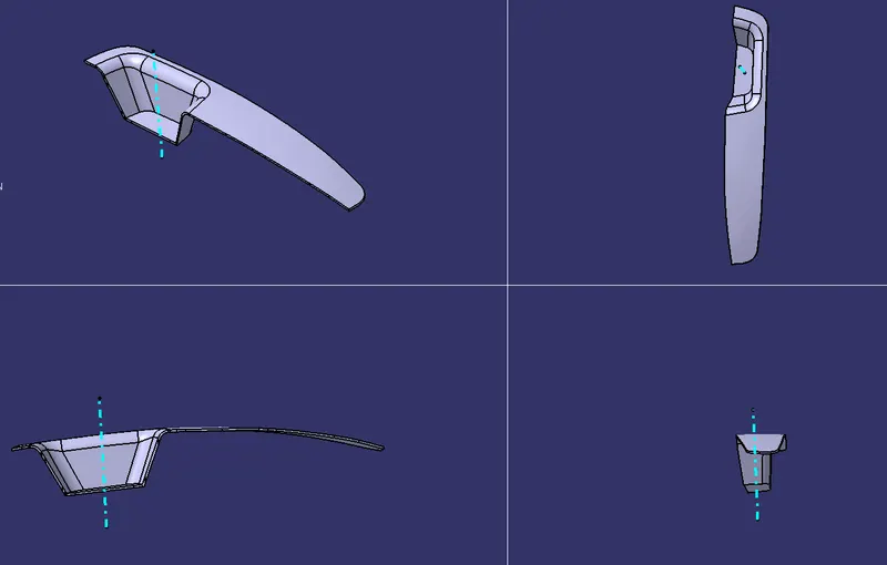
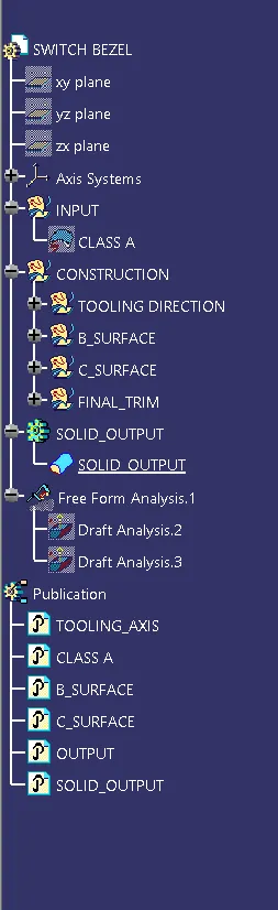
STRUCTURE TREE:
FINAL DRAFT ANALYSIS:
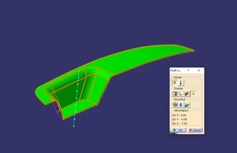
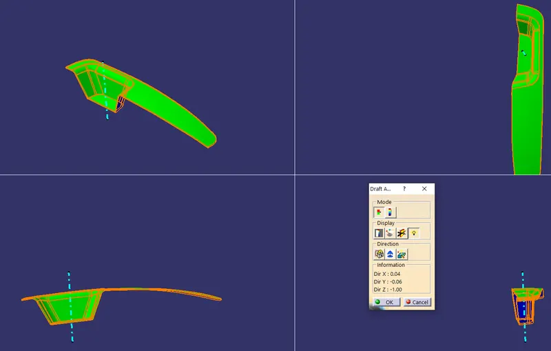
Finally the draft analysis has to be performed on the solid model that we get as a output and below image are attached. We achieved the requirement.
The green colour area shows that it satisfies the 3 - degree draft angle.
PUBLICATIONS:
CONCLUSION:
Thus the above challenge has been finished with the proper input and all the required documents are attached.