Week 4:- Pin Unit Design Challenge
CONCEPT OF FIXED PIN UNIT AND RETRACTABLE PIN UNIT
OBJECTIVE:
To design 2 different types of fixed pin unit with different pins, risers, blade & block and 2 different types of retractable pin unit with different pins, risers, blade, cylinder & block.
SOFTWARE USED:
CATIA V5
DESIGN PROCEDURE:
FORMULA & CALCULATION:
Length of the screw = [1.5 X (std. hole size)] + {distance between the surface of the part to the first surface of the other part}.
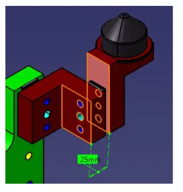
Fig 1. Length calculation for length of the screw.
To fix the pin retainer & shim block using a standard screw we need to find the length of the screw using the above mentioned formula.
The highlighted surfaces shown in the figure are the {distance between the surface of the part to the first surface of the other part}.
Since, the given tap holes is M8 & the distance is 25mm.
Length of the screw = [1.5 X (std. hole size)] + {distance between the surface of the part to the first surface of the other part}.
Length of the screw = [1.5 X 8] + 25 = 37 = 40mm Allen cap screw.
Then the standard size of the screw should be 40mm for connecting the pin retainer & the shim blocks for this example.
MATERIAL USED:
In general, the materials used for pins, pin retainers, shims, shim block, blades & risers are:
- Pin: C45, EN31, SAE 8620 Steel, etc.
- Pin retainer: steel/ ASTM A-36, SS type 303 or 304, etc.
- Shims / spacer: S.A.E. 1010 CRS FULL HARD, COLD ROLLED STRIP STEEL S.A.E. 1010 FULL HARD, S.A.E. 1020 HRS etc.
- shim block: STEEL ASTM A- 36, NM stainless, STEEL ASTM A-36, SS type 3030 or 304, etc.
- Blade: STEEL ASTM A-36, etc.
- Riser: STEEL ASTM A- 36, etc.
HARDNESS:
In general, the hardness of the materials for pins, pin retainers, shims, shim block, blades & risers are:
55 – 60 HRC to a depth of 0.5 -0.7mm after grinding.
SURFACE FINISH:
In general the hardness of material for pins, pin retainers, shims, shims block, blades & risers are:
- pin; chrome plating, zinc coating, pins with tin codes shall have 1 to 2 microns of nitride added to surfaces.
- pin retainer: BLACK OXIDE FINISH, no black oxide finish for “SS type” components (SURFACES TO BE FLATE AND PARALLEL 0.015 mm T.I.R)
- shims/ spacer: BLACK OXIDE FINISH (SURFACE TO BE FLATE PARALLEL TO WITHIN 0.015 T.I.R.
- Riser: SURFACES TO BE FLAT, PARRALLEL & PERPENDICULAR TO WITHIN 0.015 T.I.R.
PIN TOLERANCE:
The pin tolerance for a geo pin will be of closer tolerance i.e -0.15mm & for respot pin is -0.28mm.
PURPOSE OF PIN UNIT:
- As by 3-2-1 locating principle, the introduction of two pins helps to arrest the 6 degrees of freedom (4 axial & 2 radial movements) whereas other 6 degrees of freedom are arrested by introducing minimum three supports.
- Typically, the locating pins are used to locate a body part in a position sufficiently accurate to execute a welding process.
- The body part is constrained by a set of appropriately locating pin so total constraint by locating pin should be fully constrained at all times to prevent any movement.
FUNDAMENTALS OF PIN UNIT DESIGN:
It is necessary to have two pins to locate a car panel. And here one pin must arrest 4 way (i.e 4 translation) & other must have arrest 2 way (i,e 2 rotational) of a car panel.
- Pin should engage 3 to 5mm from car part entry surface.
- All pin should be accommodated with 2 way adjustable shims irrespective of direction of arresting.
- Round pin should be used in case of 4 way arresting of car panel if the hole is round.
- Round pin can be used for 2 way arresting of car panel only if the hole is slot.
- Diamond pin should be used in case of 2 way arresting of car panel if the hole is round.
- Diamond pin should be used in case of 4 way arresting of car part if the hole is slotted.
- The axis of the car panel hole & the axis of the pin should be same in general.
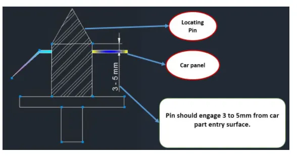
Fig . shows the 1st point in the fundamentals of pin unit design.
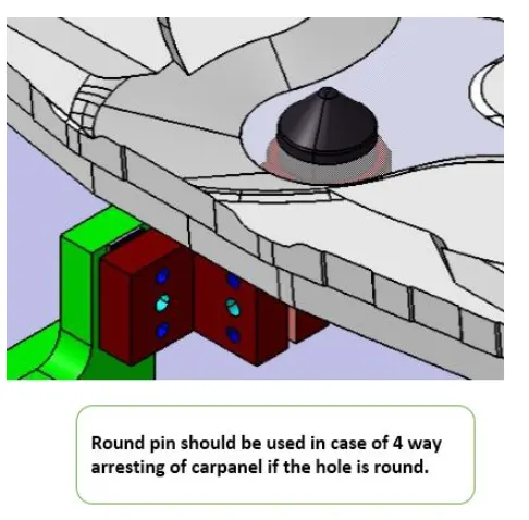
Fig . shows the 3rd point in the fundamentals of pin unit design.
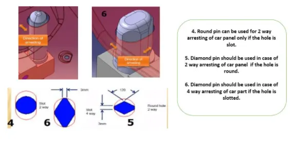
Fig . shows the 4th, 5th & 6th point in the fundamentals of pin unit design.
TYPES OF PIN UNITS:
The types of pin units are Fixed pin unit & Retractable pin unit.
FIXED PIN UNIT:
- Fixed pin unit is a unit designed to locate the car panel using pins.
- Pin, pin retainer, shims, blocks, blade, riser are the part of fixed pin units in general.
- Pin retainer is used to hold the pin firmly.
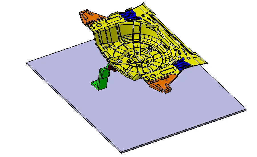
Fig . shows the principle locating point (PLP) in fixed pin unit.
Principle locating points is a hole in which we locate the panels. PLP holes must be very much precise.
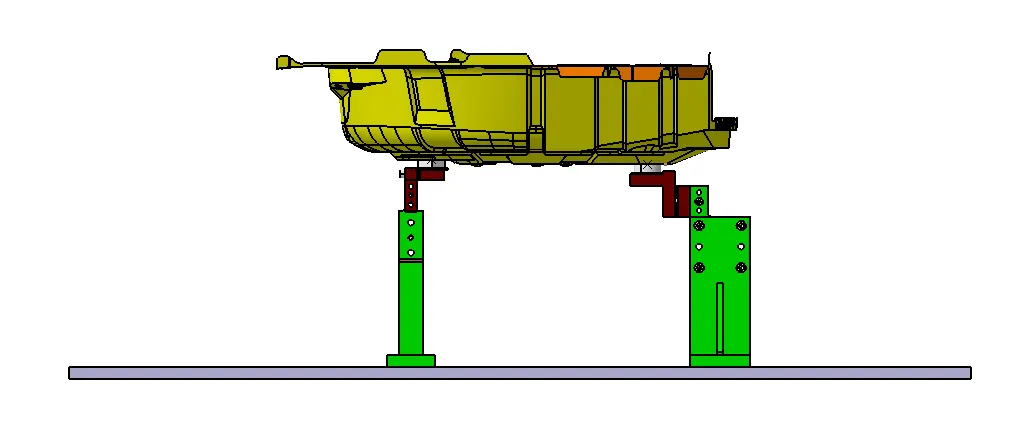
Fig . Fixed pin unit with panel.
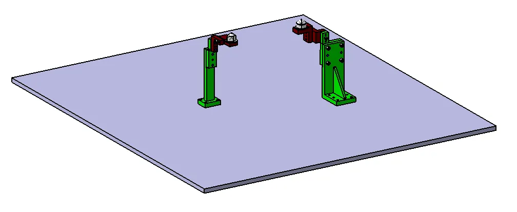
Fig . Fixed pin unit without panel.
As per the objective the 2 different types of fixed pin units
(P00_Z01_ST10_01_00) & (P00_Z01_ST10_02_00) with different pins, pin retainers,
blades& risers are designed and those fixed pin units CAD model used in this projects are
shown below in the form of picture.
PICTURES OF FIXED PIN UNIT – 1 (P00_Z01_ST10_01_00):
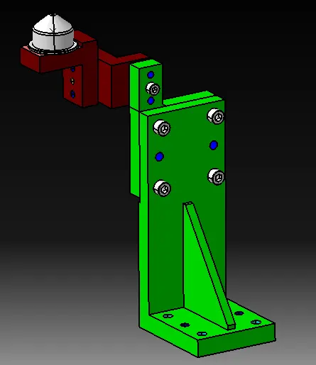
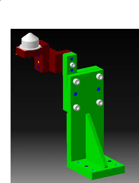
Fig . Before & after rendering of fixed pin unit – 1 (P00_Z01_ST10_01_00).
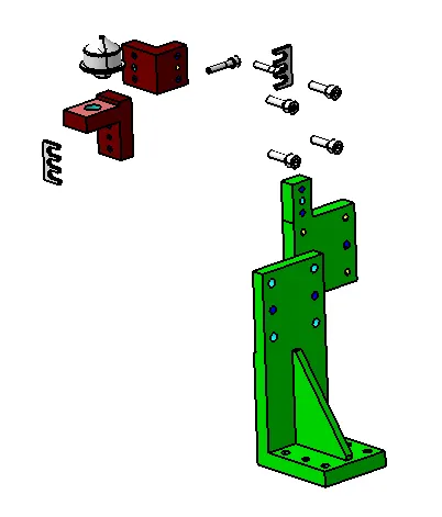
Fig . Exploded view of fixed pin unit – 1 (P00_Z01_ST10_01_00).
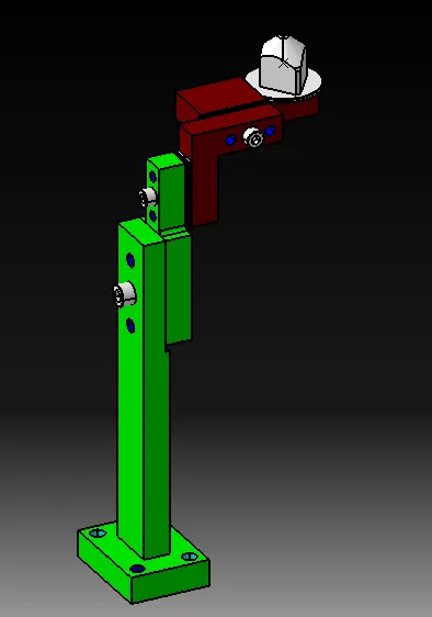
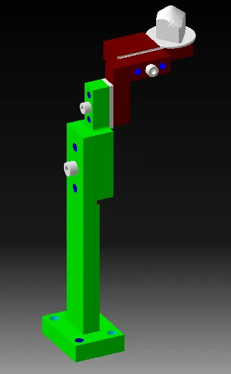
Fig . Before & after rendering of fixed pin unit – 1 (P00_Z01_ST10_02_00).
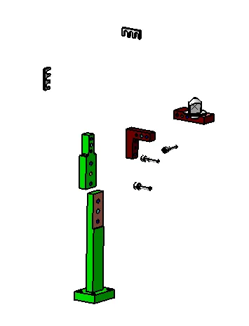
Fig . Exploded view of fixed pin unit – 1 (P00_Z01_ST10_02_00).
DIFFERENT PARTS OF THE FIXED PIN UNIT:
The different parts of the fixed pin units are as follows,
- Pin.
- Pin retainer.
- Shims.
- L-block.
- Blade.
- Riser
1. Pin:
- It is used for the location purpose of the panel.
- Typically, the locating pins are used to locate a body part in a position sufficiently accurate to execute a welding process.
- The body part is constrained by a set of appropriately locating pin so total constraint by locating pin should be fully constrained at all times to prevent any movement.
- There are dozens of styles of locating pins that can be utilized in a design. Below I have shown the commonly used pins.
One of the most common pins is a stepped pin with either small or large head.
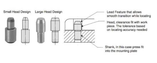
FIG . Types of Locating pin
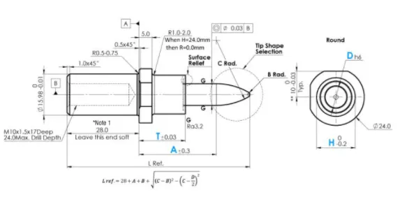
FIG . NAAMS standard locating pin (6way small head) – Make: MISUMI
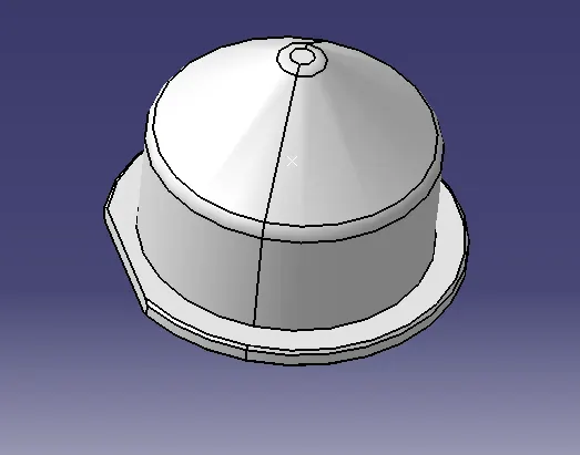
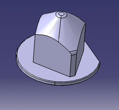
Fig . Locating pins used in this projects
2. Pin retainer:
A pin retainer is a part which holds the pin in position, the pin retainer can either be a make part or a standard part also.
Pin retainer is used to hold the locating pins firmly.
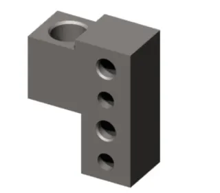
FIG . NAAMS standard – Pin retainer
Consideration while designing & manufacturing of pin retainers:
- Pin retainer should have a hole with a fit, on to which the pin will be fixed.
- The pin mounting surface of the pin retainer should be a fine machined surface.
- The pin mounting surface of the pin retainer should have the step to lock the rotation of the pin.
- The pin mounting surface of the pin retainer to the blocks should be a machined surface.
- The pin retainer will be fixed to a block or a L-block to the riser with 2 dowel holes & at least with one screw hole to maintain the tolerance.
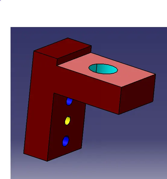
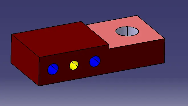
Fig . CAD model of different types of make pin retainer used in this project
3. Shims:
- In general, a shim is a thin and often tapered or wedged piece of material, used to fill small gaps or spaces between objects.
- Shims are typically used in order to support, adjust for better fit, or provide a level surface.
- Shims may also be used as spacers to fill gaps between parts subject to wear.
- Shims are the small parts which comes with the thickness of 0.1mm, 0.2mm, 0.5mm, 1.0mm etc.
- These will compensate the stack up tolerance which reflects at the mylars.
- We give tolerances to all parts of the fixture. Due to this tolerance the mylars will either lift up moves down from its defined position.
- To adjust the mylars for getting the defined position we use shims.
- Shims will be added above the mylar for adjusting according to tolerance.
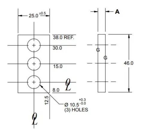
FIG 4. Shims
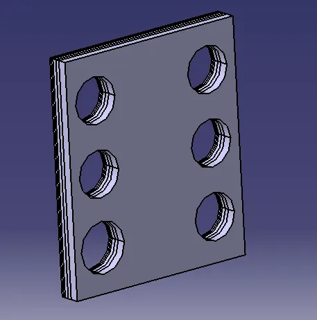
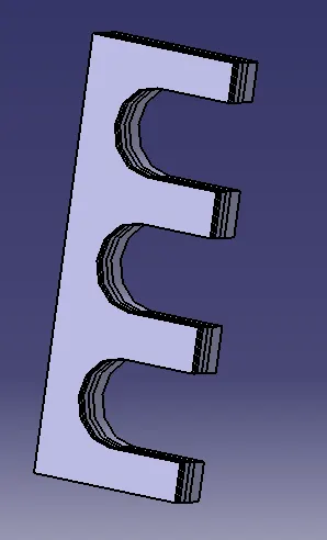
Fig . CAD model of make shim pack used in this project
4. L – Block / block:
- These parts are mainly used to accommodate the shimming directions as per fundamental in general.
- Also in some cases used for other design feasibility.
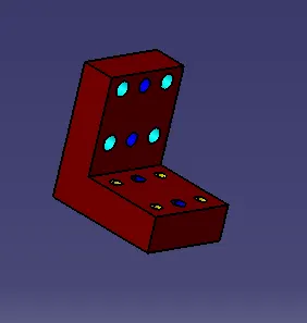
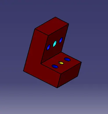
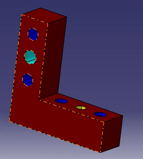
FIG . CAD model of different types L-blocks used in this project.
5. Riser:
- Riser is a manufacturing part used to raise / height the assemblies of fixture.
- One end of the riser will be attached to the base unit while the other end of the riser will be attached to the blade.
- It is a part on which all the parts of a unit are mounted on the base plate of a tool.
- In general, the riser can either be a make part or a standard part.
- Riser can be of two types. They are,
- ‘L’ type risers.
- Square tube risers.
L TYPE RISERS: L type risers are of welded type. Where the stiffner will be added at the centre for support, as shown in the below figure the wedge shaped structure is known as stiffner which is used as a support/to withstand load.
Square tube risers: Square tube risers are of frame type.
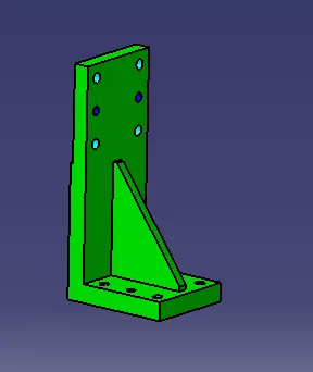
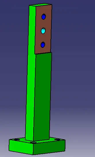
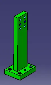
Fig . CAD model of make riser pack used in this project
6. Blade:
- Blade are the plates which is used to connects the parts of a unit to a riser. In general, the blades are the plates can either be make part or a standard part.
- Blades are the plates which are attached to riser.
- Blade is also attached or mounted with cylinders, arms etc.
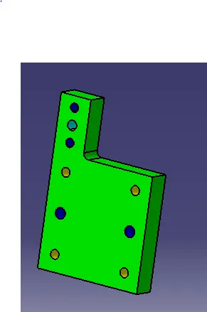
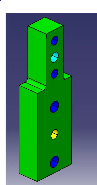
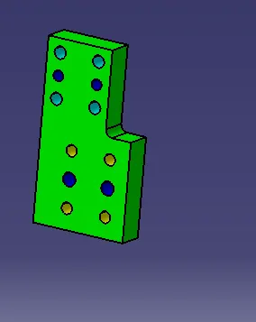
FIG . CAD model of different types of make Blade / adapter used in this project.
Hence, the different parts of fixed units are explained in detail.
Dowel holes & machined surfaces in pin unit:
- All make parts which are to be assembled with tolerance should be designed with 2 dowel holes & at
- least of 1 to 6 threaded or free hole (depends on size). And to be fine machined for the mounting surface with 3 to 5mm step machining (SURFACES TO BE FLAT, PARALLEL & PERPENDICULAR TO 0 WITHIN 0.015 T.I.R).
BOUGHT OUTS:
Bought outs used in this projects to design a pin unit are,
- Cylinders.
- Fasteners.
1. Cylinders:
SZK_30_8_T12_TUENKERS (Make: TUENKERS): Pneumatic cylinder in aluminum block design with precision guide of the piston rod, secured against rotating. Compact housing made from high-strength aluminum with mounting options on several sides. Drive mechanism with circular-section cylinder for thrust forces and extraction forces of approx. 350/250N. total stroke 40mm. integrated inductive sensing system.
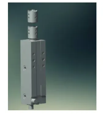
Fig. Pneumatic cylinder – std: SZK_30_8_T12_TUENKERS
SZK_40_1_BR3_A32_T12_TUENKERS (Make: TUENKERS): Retract cylinder with side mounting on piston rod for offset centering pins, flat housing of high- strength aluminum material, drive via oval-shaped oblong cylinder DIA 40/63 for thrust and tensile forces of up to approx.. 1200 N, push rod secured against twisting double-supported in bronze bushings, integrated inductive sensors, guide rod secured against twisting, 40mm combined stroke 40mm, intermediate stroke lengths upon request.
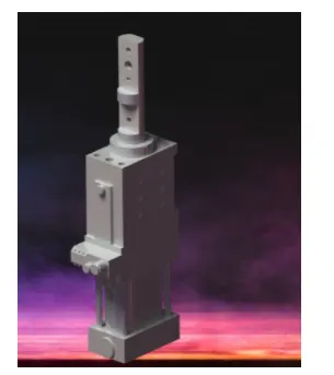
Fig . Pneumatic retract cylinder – std: SZK_40_1_BR3_A32_T12_TUENKERS
2. Fasteners:
Hexagon Allen Cap Screw (ISO 4762 STEEL HEXAGON SOCKET HEAD CAP)
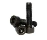
Fig . Fasteners
CONCLUSION:
Hence, as per the objective to design 2 different types of fixed pin unit with different pins, risers, blade & block (P00_Z01_ST10_01_00) & (P00_Z01_ST10_02_00). and 2 different types of retractable pin unit with different pins, risers, blade, cylinder & block (P00_Z01_ST20_01_00) & (P00_Z01_ST20_02_00) are designed and rendered by using CATIA V5 successfully.