Challenge

Week 8 - Challenge 3 - Switch Bezel Design

Aim
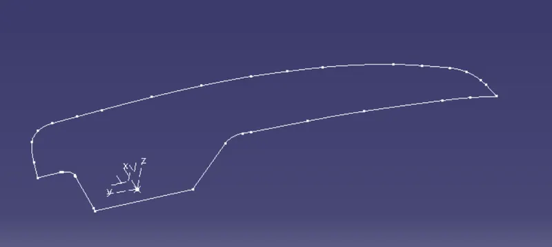
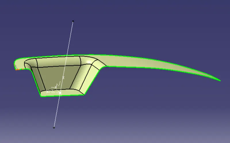
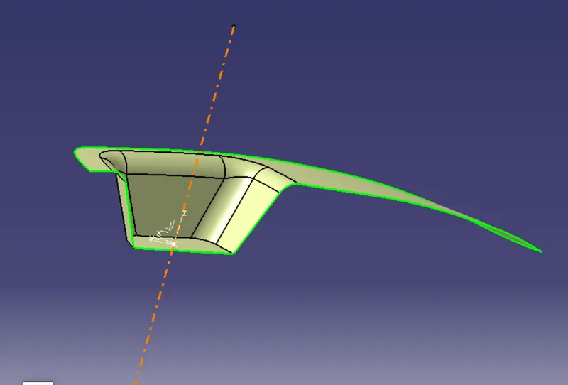
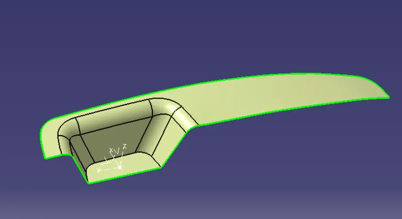
Create the tooling axis for the given switch Bezel and design Class B and C surface meeting the requirements of the draft angle and perform the Draft analysis on the model.

Introduction

Having easier ejection from the mold may seem like a minor concern, but draft is crucial to manufacturing parts that meet your quality standard. Without draft, major problems can arise in the injection molding process that increase the time and cost of production.

When no draft is designed into the part, problems can come from friction and vacuums. These issues can damage both your part and even your mold in extreme cases. These problems are a direct result of having insufficient draft. Because plastic shrinks as it cools, portions of the part may pull away from the mold while others grip the core. If there is no draft angle that allows a simple push from the ejector pins to pop the part out of the mold, the part’s surfaces will often drag along the mold as it is being ejected. This friction between the two surfaces can cause scratches or gouges in your part and affect the appearance. This is particularly troublesome if your part is being molded with a surface finish or texture. The friction will scrape away texture and leave you with many rejected parts.

Recommended draft angle
3 degree is the nominal draft
0.5 is the nominal draft
Above 5 degree for textured face
Procedure followed for draft analysis
1)check for any gap between the surfaces and make sure there is no gap by visually or by checking with boundary feature if the gaps are found out make sure to joined
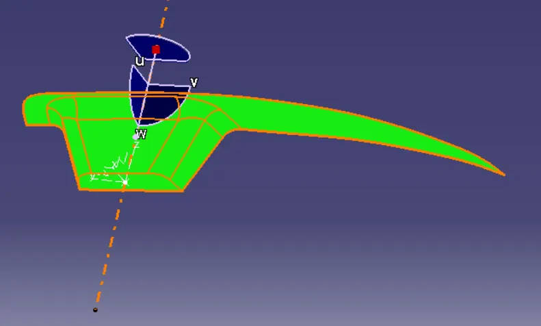
2)Creating the best possible dummy Axis(Makeing sure there are no undercuts)
Reference tooling axis called dummy tooling axis is created for refrence
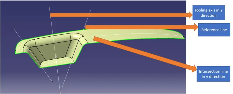
3)Creating axis in Y direction
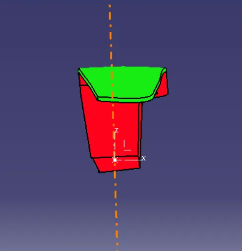
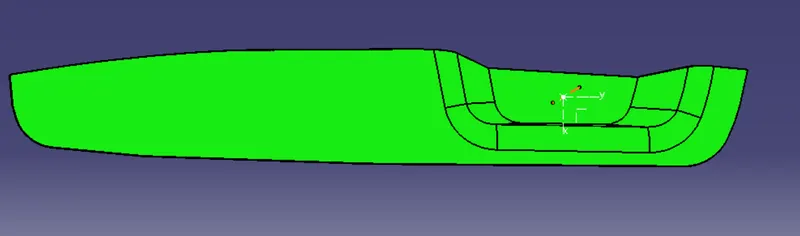
creating the intersection in y direction and creating two reference lines on the region of the intersection were it is almost parallel to the Z direction.
once the refrence lines are created the next procedure is to create Y tooling axis in Z direction(which means tooling axis perpendicular to the intersection profile along Y direction)
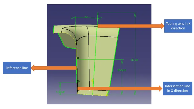
4)Creating axis in X direction
Creating the intersection in X direction and creating one reference line on it were it is almost parallel to the Z direction
once the refrence line is created the next procedure is to create X tooling axis at 5 degree from the refrence line in Z direction(which means tooling axis is perpendicular to the intersection profile along X direction)
Final tooling Axis
The final tooling axis we get by bisecting the X tooling and Y tooling axis

Class A surface Analysis

Class A surface analysis is done to ensure that it has no negative draft for the selected tooling axis

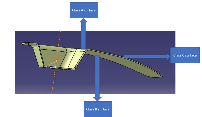
Designing the class B surface from the given class A surface is the next step to be followed

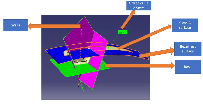
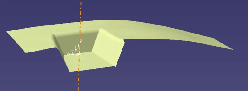
  • As the fillets gives problem during the thickening we extract the walls base and the bezel rest surface and offset all the three surfaces towards the class B region by 2.5mm and trim them and provide the necessary fillets following the rule(Radius of the fillet of class A surface) ±(the offset value) to get the class B surface
After providing the fillets and the final trim class B looks as show below
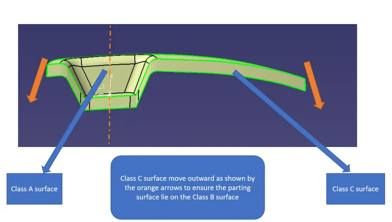
Class C surface
Class C surface are once which lies between the Class A and B surface . while creating the class C surface we have provided the draft greater than 3 degree in such a way that the parting line lies at the B surface. And this is done to prevent flash on the Class A surface.
Class A , B , C surface after the final trim
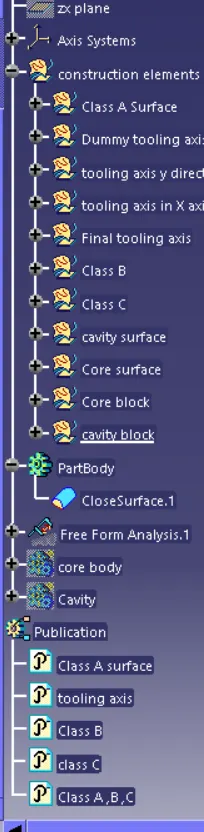
Tree Structure
Publication is done as it is easy to access the tooling axis and the Class A surface
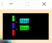
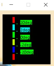
Colour scale which indiactes the degrees at sepecific location
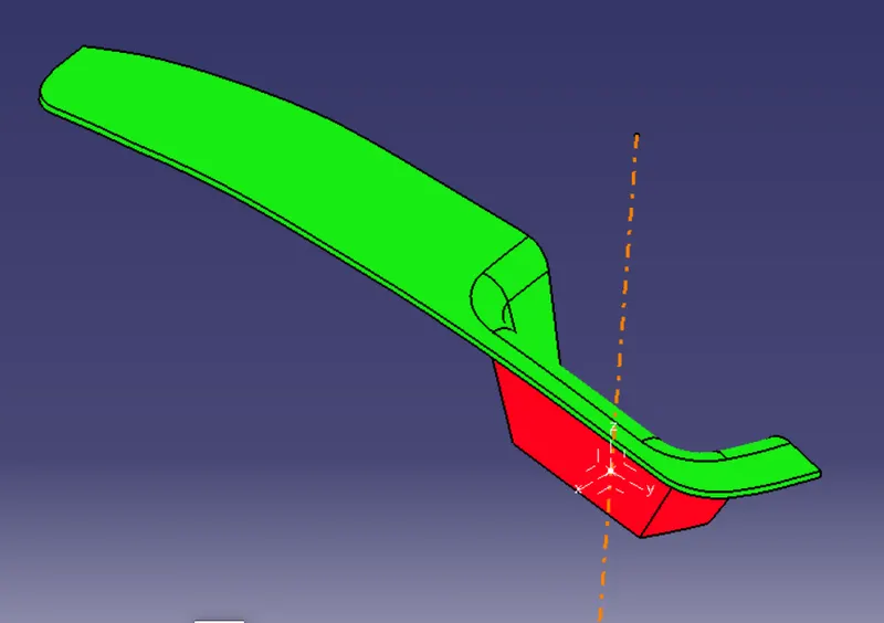
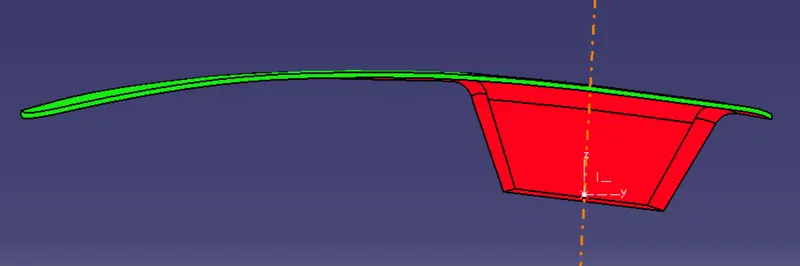
Draft angle in various orientations
Isometric
Front
side
Top
once the solid body is designed the draft analysis is carried out ensure that it has no negative draft and if it has no negative draft then the component is manufacturable.All the region of the Switch bezel are of the same colour on one side which indiactes that it has more than 3degree draft.
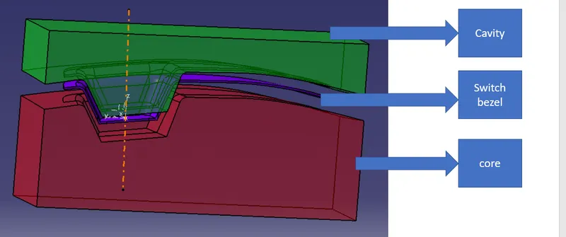
Mold design designed for the Switch Bezel
while designing the mold it is made sure the core is at the B side of the component
Reason?
To have the ejector marks on the Class B side.

Conclusion

The Switch Bezel class B and C surface and a solid body was designed sucessfuly from the give Class A surface and the mold was designed for the same

Your portfolio, next

Ship work like this
in your own course.

Talk to a career counsellor

Free 20-minute call. We'll map the right course to where you want to work.

By submitting you agree to our Terms and Privacy Policy.

Talk to a career counsellor

Free 20-minute call. We'll map the right course to where you want to work.

By submitting you agree to our Terms and Privacy Policy.