Week 8 - Challenge 3 - Switch Bezel Design
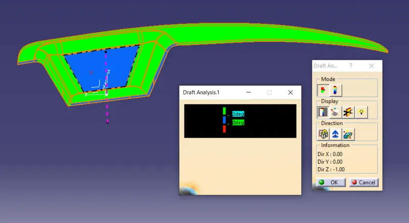
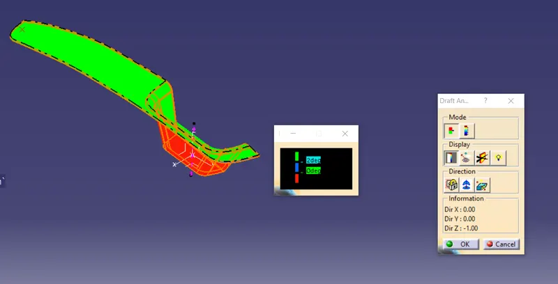
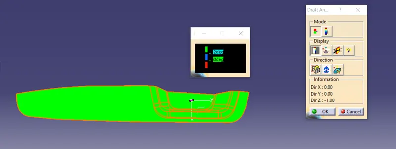
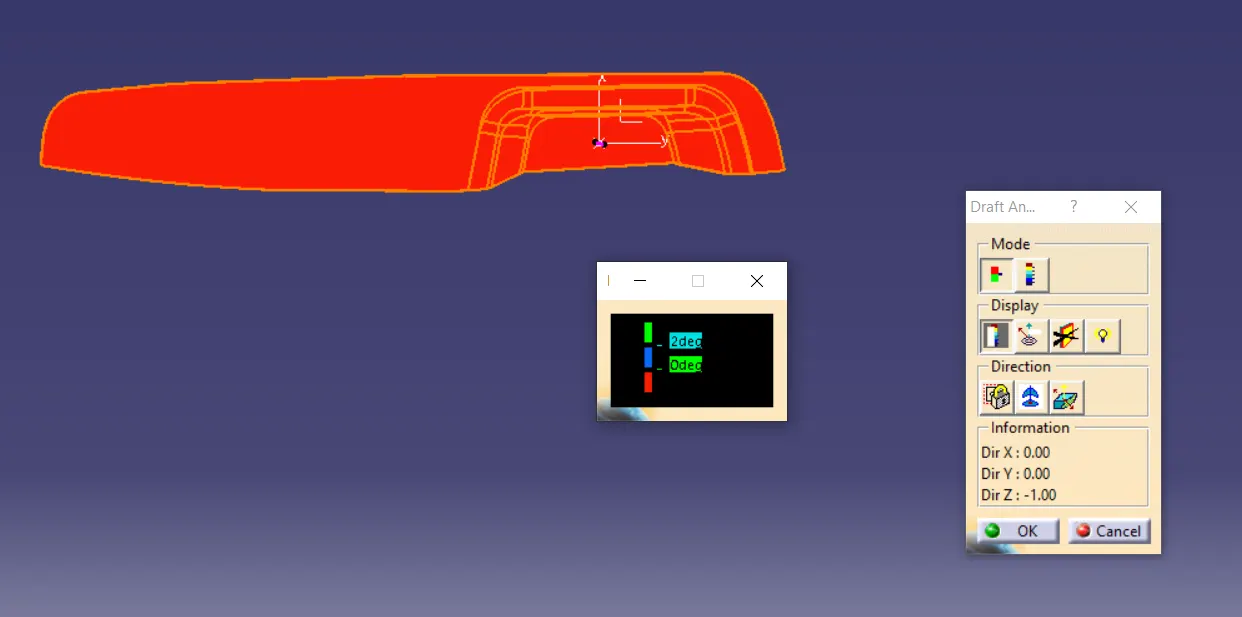
Subject:- A report on draft analysis of class A surface and final part along with tooling direction cretion.\
Answer:-
Creation of tooling direction:-
The tooling direction of an parts should be such that the there will not be an undercut in the part i.e the tool get easly removed after solidification of the part in mold cavity.
The tooling direction decided based on following consideration.
- The half of the part should be in cavity and the other half in the core.
- The hole should be considered along the direction of the tool movemenet.
- There should not be any undercut in the part.
- The maximum area of the part should be covered within main tooling.
example of tooling direction .
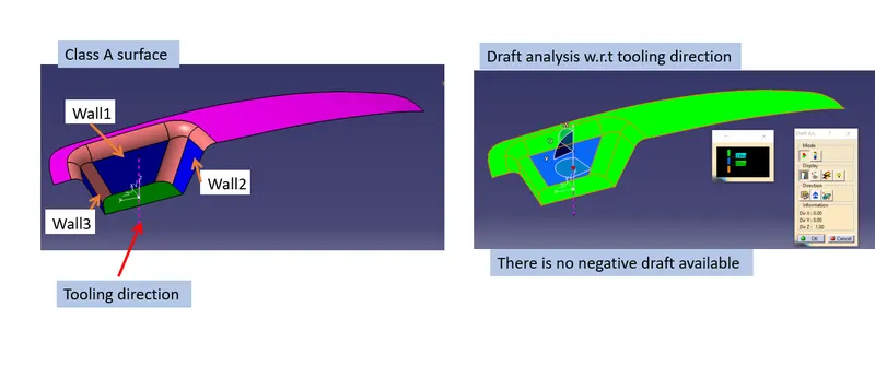
Creation of tooling direction using Bisection method.
Step 1:-
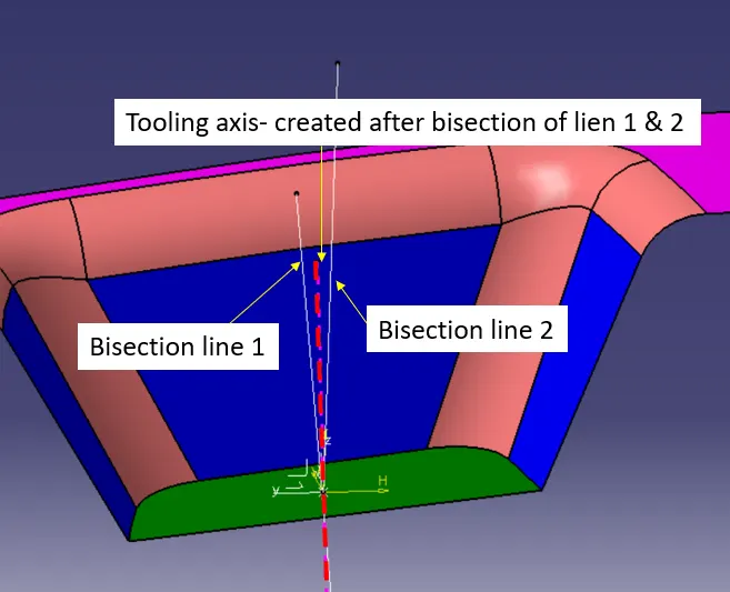
To create the bisecting tooling direction first step is to sxtract the base surafe , then an mid point on the extraxtes surface created .After that an new axis system inseted at that point.
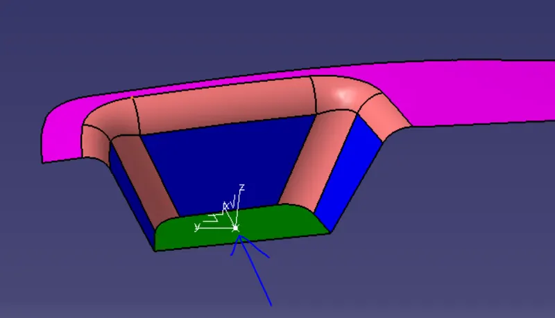
STEP 2:-
In second step a intersection line created between walls in Y direction and y-Z plane using sketch, form the intersection lines on walls, two line created i.e one from left wall intersection and second from right wall intersection, then one common line with bisection line commond get generated.
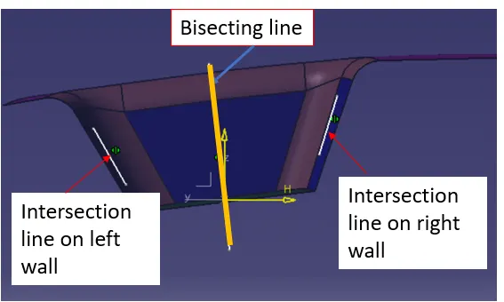
STEP 3:-
In third step a second intersection line created between walls in x direction and X-Z plane using sketch, one line created from the intersection curve using sketch commond.Then from the projection point at the base plane one line created parralel to intersection line using 3deg draft ange .
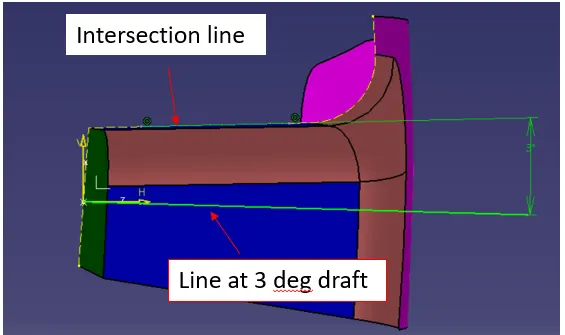
Step 4
AT the last stage a common line created by using bisecting of line common and thet is the tooling axis of the part.
Draft analysis :-
Class A surfface
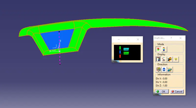
Draft analysis of part