Engine kinematics of Otto cycle
Aim: To write a MatLab program to calculate the thermal efficiency of the Otto cycle and plot the processes on the P-V diagram
Otto cycle:-Otto cycle is a basic air standard cycle used in four-stroke engine which comprised constant volume heat addition and constant volume heat rejection. The Otto cycle consists of isentropic compression, heat addition at constant volume, isentropic expansion, and rejection of heat at constant volume. there are some assumptions we have to take for the calculation of work output and thermal efficiency of the Otto cycle.
Assumptions:-
1- The working fluid is air, Air is considered an ideal gas.
2- The specific heat constants are not changing with Temp.
3- The mass of the gas is fixed.
4- All processes are reversible.
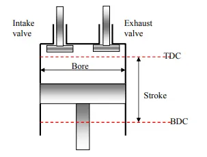
Terms basic term used in piston-cylinder arrangement shown in below fig.
TDC= Top dead center
BDC= Bottom dead center
Bore:- Internal dia of Cylinder
Stroke= Distance between TD to BDC.
Swept volume=Volume between TDC to BDC
Clearance volume =Volume left out inside the cylinder when the piston is at TDC.
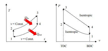
Otto cycle T-S and P-V diagram and process.
The Otto cycle consists of four internally reversible processes in series:
1-2 Isentropic compression
2-3 constant-volume heat addition
3-4 Isentropic expansion
4-1 Constant-volume heat rejection
The Otto cycle is executed in a closed system and the working fluid is air according to the air-standard assumption. Also, changes in kinetic and potential energies are negligible. No heat transfer is involved in the two isentropic processes. The energy balances for these two processes are:
-w12 = u2 - u1
-w34 = u4 - u3
w12 is negative since work is needed to compress the air in the cylinder and w34 is positive since air does work to the surroundings during its expansion.
In the constant volume heat addition and heat rejection process, no work interaction is involved since no volume change occurs. The energy balances for these two processes are:
q23 = u3 - u2
q41 = u1 - u4
q23 is positive since heat is added to the air and q41 is negative since heat is rejected to the surroundings.
The thermal efficiency for an ideal Otto cycle is
ηth, Otto = wnet/qin
According to the analysis above, the net work output is
wnet = w34 + w12 = q23 + q41
qin = q23
ηth, Otto = 1+ q41/q23
Under the cold air-standard assumption, the thermal efficiency of the ideal Otto cycle is
Process 1-2 and process 3-4 are isentropic. Thus,
K= isentropic constant (Cp/Cv)
Since v2 = v3 and v4 = v1,
Considering all the relations above, the thermal efficiency becomes,
Input function :
Volume is an function of crank angle , when cranck angle increases from zero to 180 (i.e piston moving from BDC to TDC) the inclosed volume of decreases .
Below is the engine kinematics relation shows the variation of volume with crank angle.
VVc=1+(r−1)[R+1−cos(θ)−(R2−(sind(θ)2)0.5
function [V]=engine_kinematics(bore,stroke,cone_rod,cr,crank_start,crank_end)

%V/Vc= {1+0.5(cr-1)[R+1-cosd(theta)-(R^2-(sind(theta)^2)^0.5)}}
%R=Ration of connecting rod length/crank radious
%theta=crank angle
a=stroke/2;
R=cone_rod/a;
v_swept=pi/4*bore^2*stroke;
v_clearance=v_swept/(cr-1);
theta=linspace(crank_start,crank_end,100);
term1=(cr-1);
term2=R+1-cosd(theta);
term3=(R^2-sind(theta).^2).^0.5;

 V=(1+0.5*term1.*(term2-term3)).*v_clearance;

end
Main program to calculate the Efficiency and P-V diagram
% otto cycle
clear all
close all
clc

bore=200                       % Inside dia of cylinder
stroke=100                     % Stroke of cylinder(TDC-BDC)
cr=12                          % Compression ratio
cone_rod=300                  % Length of connecting Rod
Y=1.4                        % Isentropic constant for air
P1=101325
T1=300                       % Inlet temp
T3=2300                       % Max temprature

V_swept=pi/4*bore^2*stroke ;    % Swept volume (Volume between TDC to BDC)
V_clearance=V_swept/(cr-1);     % Clearance volume
V1=V_swept+V_clearance        % Total volume

% state condition at point 2 (P2, V2, T2)

V2=V_clearance

P2=P1*cr^Y;
T2=T1/cr^(0.4/Y)             % P1*V1^Y=P2*V2^Y ---(PV=mRT)---(P=mRt/V)

const_c1=P1*V1^Y;             % During isentropic process PV^Y=C
%input calling function for isentropic compression
V_comp=engine_kinematics(bore,stroke,cone_rod,cr,180,0) ;
P_comp=const_c1./V_comp.^Y;

% state condition at point 3
V3=V2                         % For otto cycle constant volume heat addition
P3=T3*P1/T2                  % For constant volume P1/T1=P2/T2

% Isentropic expention process
const_c2=P3*V3^Y;             % During isentropic process PV^Y=C
%input calliing function
V_exp=engine_kinematics(bore,stroke,cone_rod,cr,0,180)
P_exp=const_c2./V_exp.^Y      % PV^Y=C

% state condition at point 4
V4=V1;                        % Constant voluem heat rejection
P4=P3/cr^Y                   % Process 3->4 isentropic expansion% PV^Y=C

% efficiency of Otto cycle

n=1-1/cr^(Y-1)


figure(1)
hold on
plot(V1,P1,'*','color','r')
plot(V_comp, P_comp)
plot(V2,P2,'*','color','b')
plot(V3,P3,'*','color','r')
plot([V2 V3],[P2 P3])
plot(V_exp, P_exp)
plot(V4,P4,'*','color','b')
plot(V1,P1,'*','color','g')
plot([V4 V1],[P4 P1])
xlabel Volume(m^3)
ylabel Pressure(Pa)
title("efficiency of Otto cycle=63%")
grid on
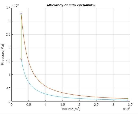
The output of the program is efficiency which is 63%.
Conclusion:-
With the help of above figer its concluded that the variation of pressure and volume is non linear for compression and expansion process which results in non linear behaviour of Temp .The design of the piston cylinder arrangement should be done by considering the non linear behaviour of pressure and temp , rather than consideing the linear vehaviour.
The efficinecy of of an ideal system is in teh range of 55 to 65%, but in the actual case its 25-35% because the isentropic constant depends on specicif heat constant .the specific heat constant Cp & Cv varies with temp which results in variation in isentropic const (gamma). also losses in process are considered .