Week 8 - Challenge 3 - Switch Bezel Design
AIM :
Create the Switch Bezel Plastic component through the given Class-A surface. To begin with, the tooling axis for the given Class-A Surface should be created meeting the requirements of the draft angle and at the end perform the Draft analysis on the model.
Take the Thickness of the component to be 2.5 mm
DRAFT ANALYSIS :
- 1ST to check the connectivity of the class A surface.
- Ensure that there is no gap between the component, using join command .
- We can visually check it or by clicking boundary command.
- After that disassembled.
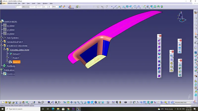
It has 2 boundary. inner and outer.
-
so the 1st design check is completed.
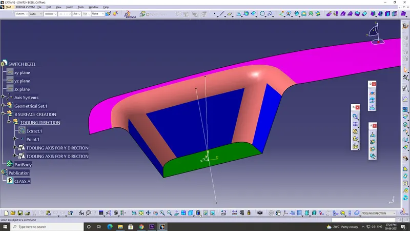
step 2: Find the toling axis of the component.The tooling axis is nothing but the mould opens or cavity opens.
- Check visually which is the best possible tooling direction.
- check all the 3 axis.
- insert the sketch along yz plane.
- intersect of the class A.
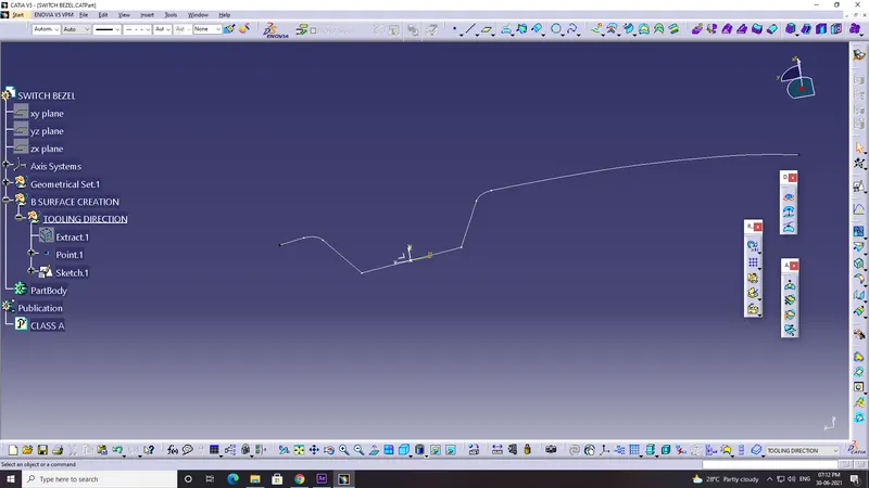
DRAW A 2 line
and create a bisecting lines make the 2 line as the construction.
exit pad
This the tooling axis for the y direction and the next do the x direction.
point the sketch.
zx plane.
Intersect the class A .
DRAW a 2 line .
give 3 deg
we have now y and x direction line.
so now bisecting the line 1 and line 2 at point 1 ok.
now we get the tooling axis.
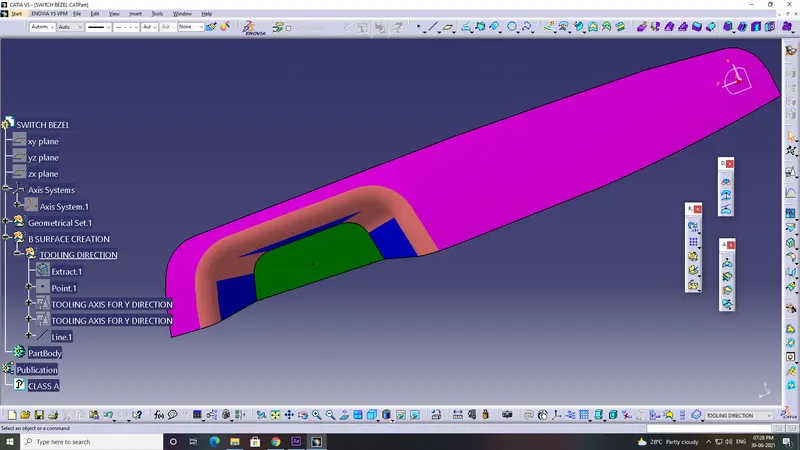
now this is the draft analyst tool.
And next place the axis and lock it.
It displayed in green color.
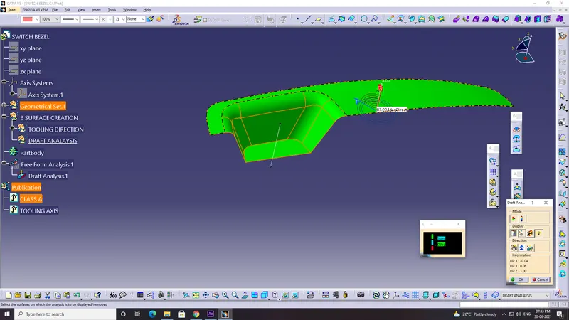
more than 3 is green.z is red and negative is blue.
minimum draft value is 3.
Now measure individually
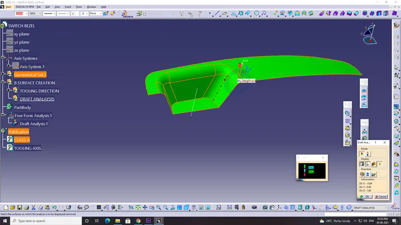
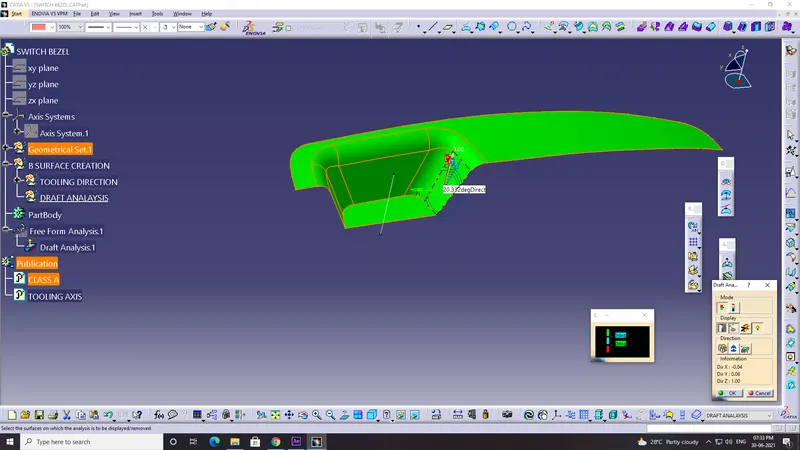
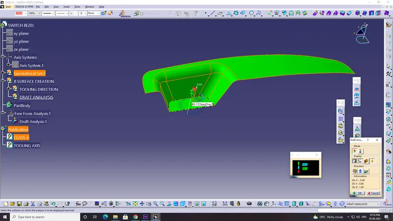
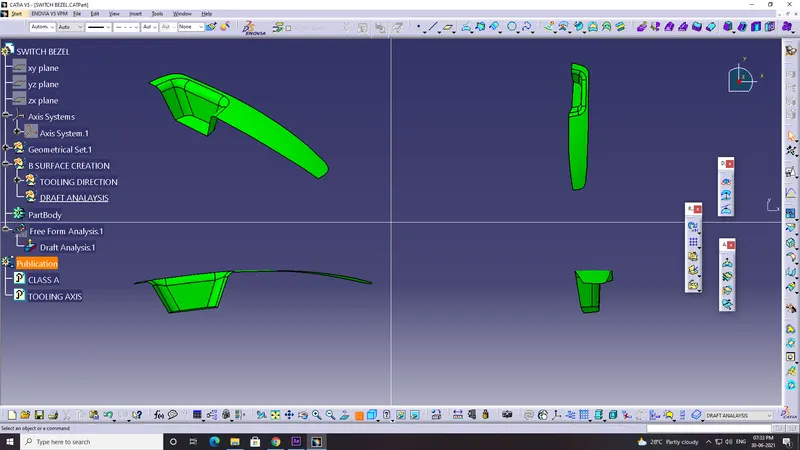
- Screenshots of the model with the proper color code of the draft angle in various orientations (Isometric, Front, Side, and Top View)
Create a geometric set and name as B SURFACE ------ BEZEL REST SURFACE.
Extract the top surface and give no propagation.
untrim the surface.
Hide the extract.
and give the offset value of 2.5mm.
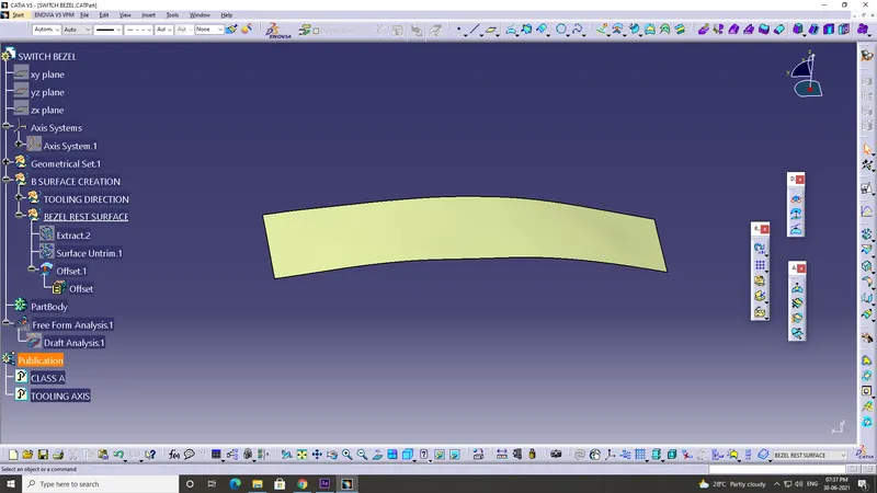
After that create apropretae for all side wall and tha base
Extract the all side walls and give no propagation.
untrim the surface.
Hide the extract.
and give the offset value of 2.5mm.
Extract the base and give no propagation.
untrim the surface.
Hide the extract.
and give the offset value of 2.5mm.
as same as above and trim it.
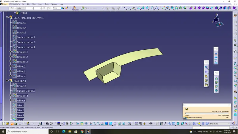
Now to give the fillet for thar measure it.
AFTER THE FILLET INSERT THE GEOMETRIC SET.
bezel ----- C SURFACE.
now select the outer boundary of the class A.
Unhide the tooling axis.
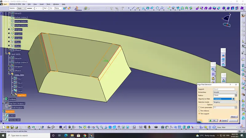
so now give the last trim of the side fillet as R15mm and top wall is 14 - 2.5 mm.
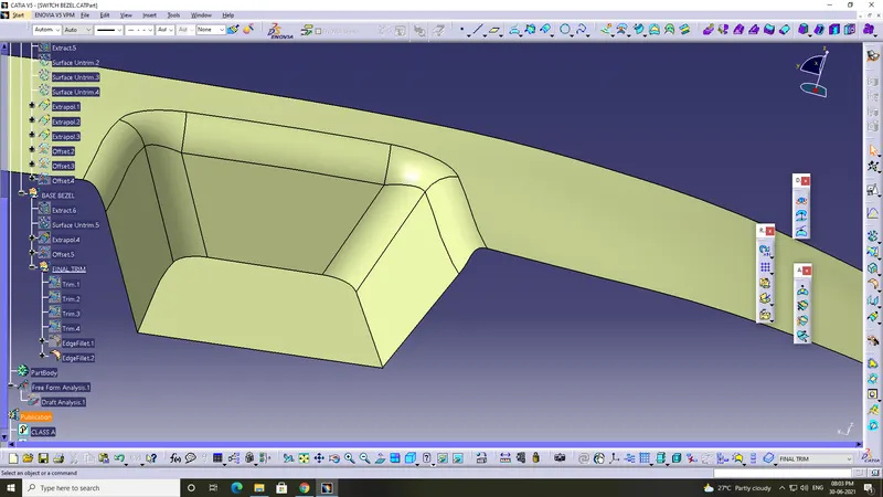
give sweep command. ensure that in profile type in 2nd one.
subtype ---- draft direction.
G.C ------ boundray.
draft direction ----- tooling axis.
whooly defined
angle 3 deg minimum
choose the botoom direction of the 1.
join SEEP and the CLASS A SURFACE. AND TRIM IT.
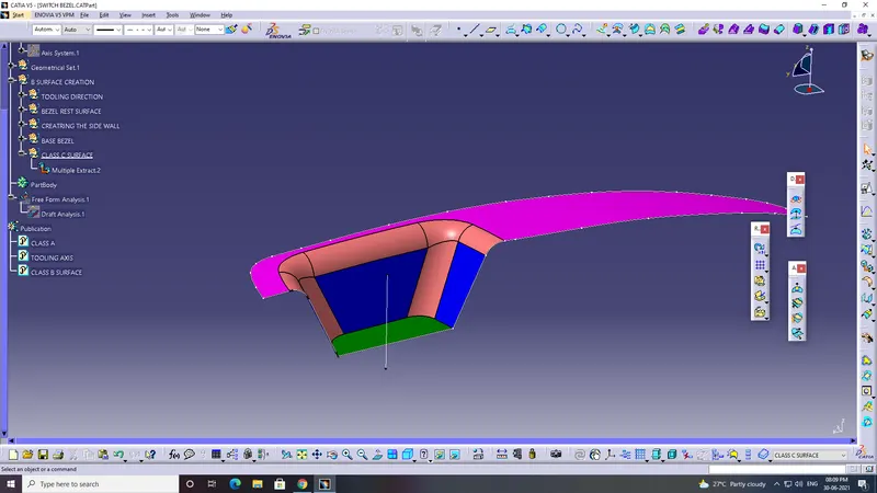
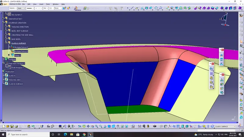
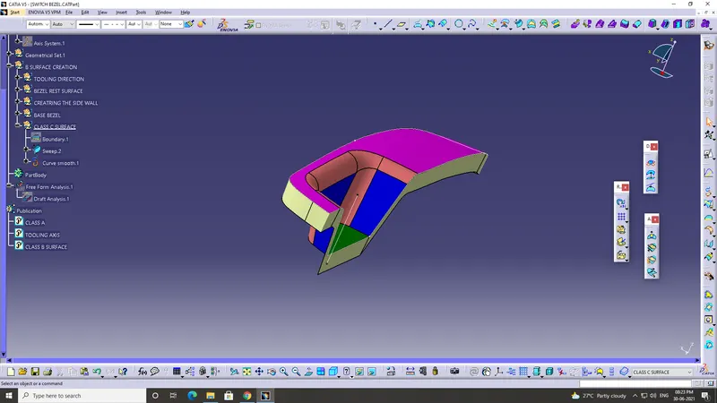
join the class a and the sweep.
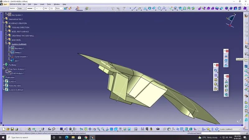
give trim it .
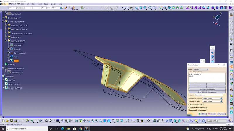
After that this surface is gonna use it for the closed surface.
so give this surface as the closed surface.
and check it.
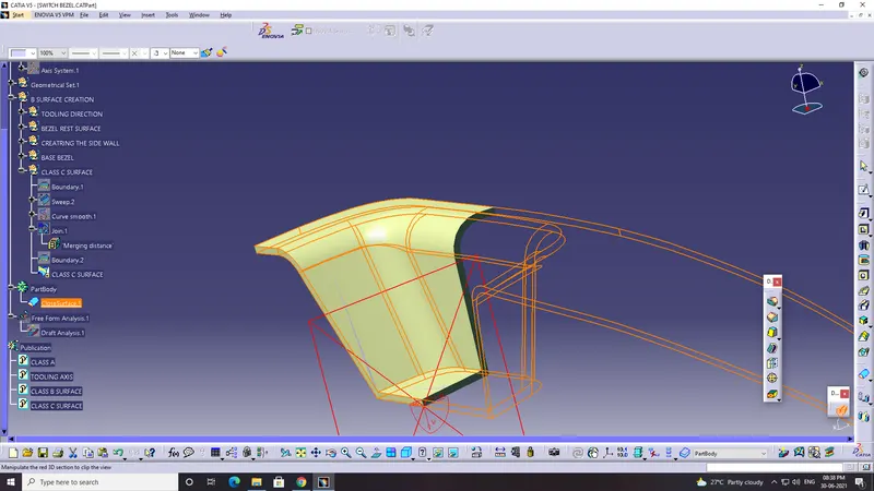
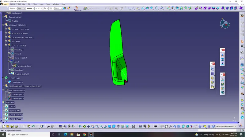
and publish the
- CLASS A SURFACE.
- TOOLING AXIS.
- CLASS B SURFACE.
- CLASS C SURFACE.
- CLOSED SURFACE.
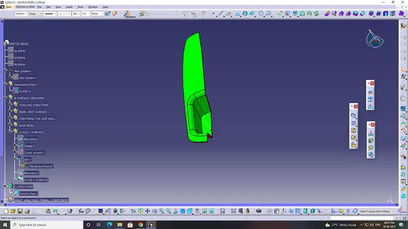
FINAL COMPONENT DRFAT ANALYSIS
now this is the draft analyst tool.
And next place the axis and lock it.
It displayed in green color.
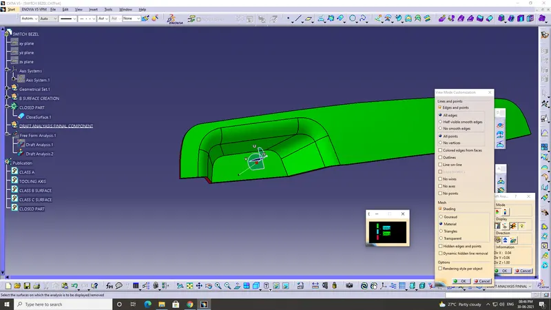
more than 3 is green.z is red and negative is blue.
minimum draft value is 3.
Now measure individually
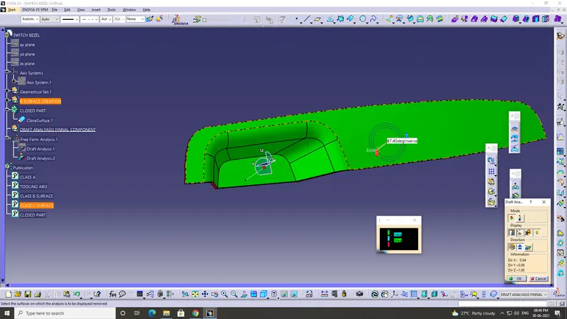
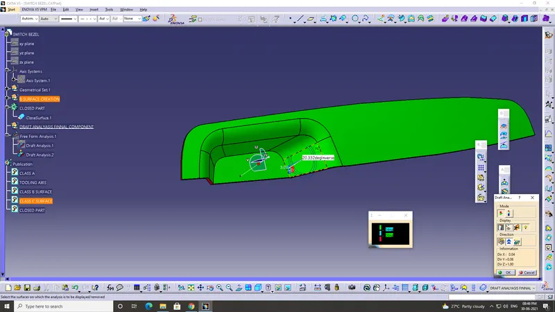
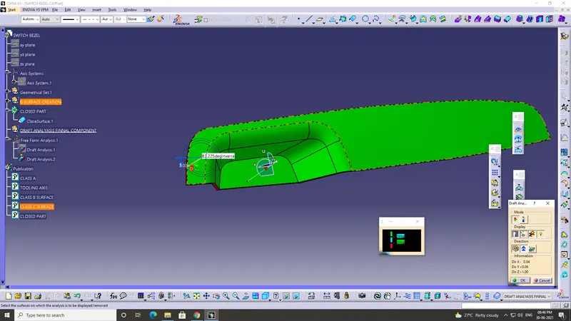
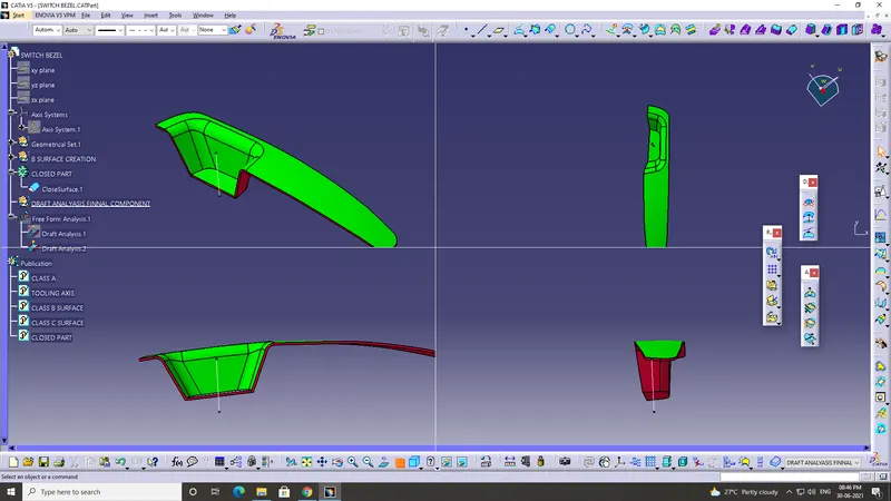
- Screenshots of the model with the proper color code of the draft angle in various orientations (Isometric, Front, Side, and Top View)
- Screenshots of the expanded Tree Structure for the Geometrical Sets and the Part Body.