Week 8 - Challenge 3 - Switch Bezel Design
DRAFT ANALYSIS OF SWITCH BEZEL & CREATION OF CLASS B AND CLASS C FROM CLASS A
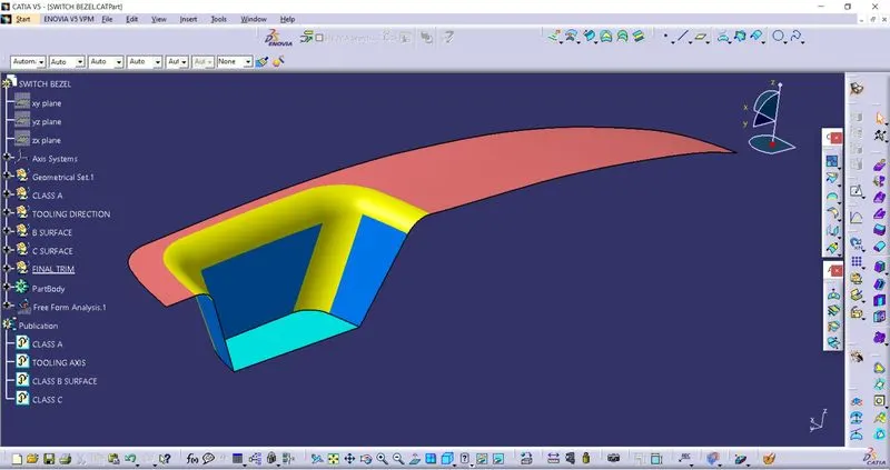
CLASS-A: The styling surface or the aesthetic surface of a component is known as Class A.
CLASS-B: The surface which contains the engineering features is known as class B.
CLASS-C: The surface which binds class A and class B together is known as class C.
At first, the given class A is inspected for continuity in its surface. The inspection is made using the boundary command. The boundary command should result in only the peripheral extracted curves. Hence, flagging to proceed to the next stage.
CREATION OF TOOLING AXIS:
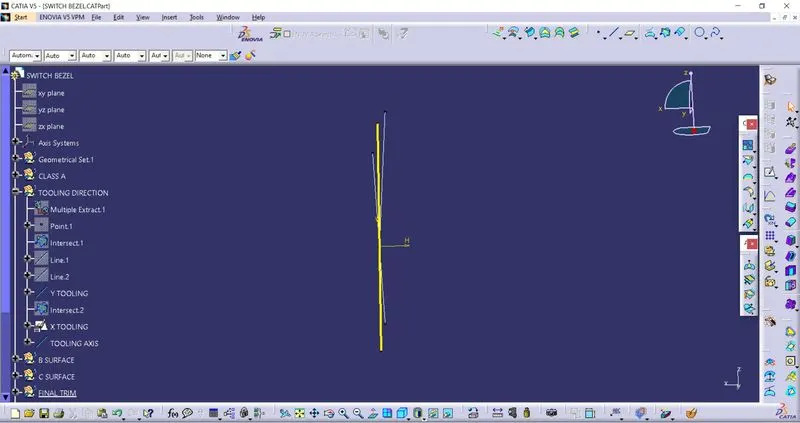
The tooling axis is created using the bisecting method. Initially, class A is taken and intersected with the YZ axis. The lines are extended on the surfaces which are likely to fail the draft. The lines are then bisected to form a single line, the Y tooling axis.
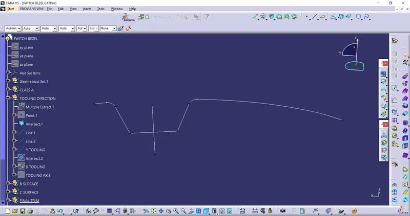
Now, to create the X tooling axis. Class A is taken and intersected with the XZ plane to form an intersection curve. A line is drawn using the positioned sketch at an angle of 7 degrees.
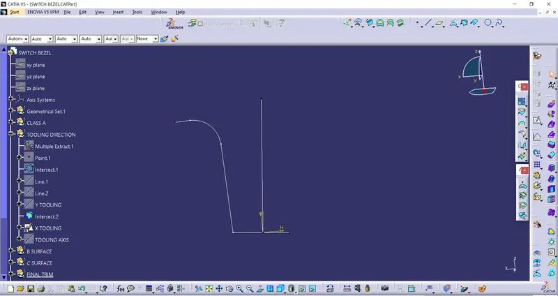
Now, both the X tooling and Y tooling axis is bisected to form the main tooling axis. The main tooling axis is published for easy access.
CREATION OF CLASS B:
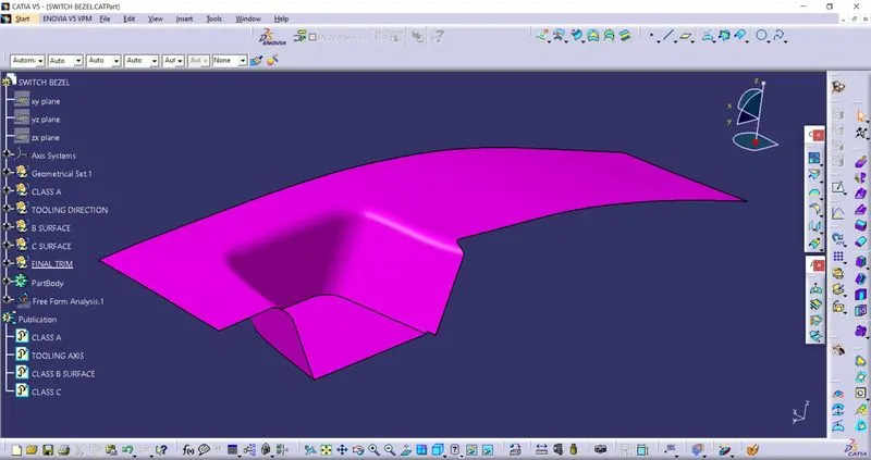
Class A is extracted, untrimmed, and extrapolated. The extrapolated surfaces are trimmed. Now, the trim is offset for the value of the thickness of the component.
CREATION OF CLASS C:
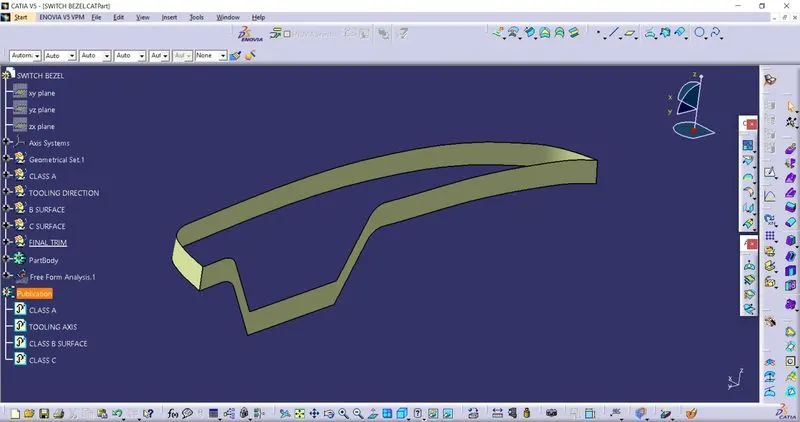
Class C surface basically joins Class A with Class B. The boundary of the curve is extracted. The curve is smoothened using smooth curves operation in order to eliminate discontinuity. The curve is then swept with respect to the draft direction or tooling axis.
DRAFT ANALYSIS ON SWITCH BEZEL.
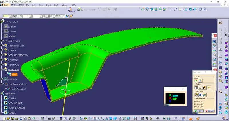
- The feature draft analysis is enabled.
- The compass is brought and aligned with the tooling axis and locked
- Now, click on any surface on the part
- The color scale is indexed
- The output is as follows
THE FINAL TRIM
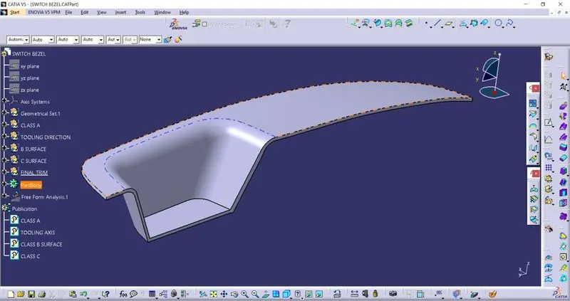
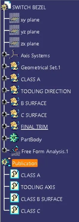
TREE STRUCTURE: