Roof challenge
DESIGN OF ROOF
The roof is one of the major parts of the car. It basically serves to protect the passengers from different weather conditions. As the roof is a long sheet metal it cannot withstand the load alone. So, the support members like bow roofs and roof rails are introduced in order to enhance the strength of the roof.
- ROOF RAIL : it is provided where the wind shield glass is housed.
- ROOF RAIL: it is the position where the back doors hinges sit.
- BOW ROOF : these are added predominantly to enhance the strength.
- REIN. CR. ROOF RAIL: these is the reinforcement are connected to the B-pillar where the car body entirely directs the force during a roll over. Keeping this in mind the reinforcement is designed to withstand the load experienced during the collision.
While designing the roof the visibility criteria line is kept in account as one of the major factors. This is basically turned in by the design team. The head room clearance of minimum 85mm is given.
TEST CONDUCTED:
The basic tests conducted are the roll over test and the roof crush test. The standards for conducting the test are ruled out by iihs. The test is conducted with doors and windows closed. The biw is taken to measure the reformation or protrusion after the test.
A slab of dimension 1800x750 mm is slowly pressurized at an angle of 25 deg side ways and 5 deg of yaw angle. It is slowly loaded against the BiW for 120 seconds and the results are computed
FMVSS 216: roof crush resistance , This standard establishes strength requirements for the passenger compartment roof. The purpose of this standard is to reduce deaths and injuries due to the crushing of the roof into the occupant compartment in rollover crashes.
There are designs of roof which includes a sunroof , panoramic roof. In this situation the requirements for the roof crush test and roll over test is met by maintaining the strength to weight ratio.
There are criteria like the heat distortion criteria and the snow load criteria which has to be accounted while designing the hood.
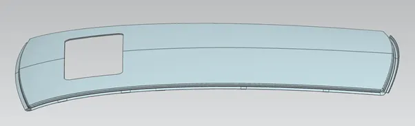
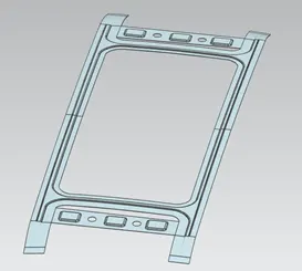
The figure depicts the roof which is designed with a sunroof. Here the strength requirements are met by introducing a panel beneath the sunroof cut out. The panel is shown below.
The roof is designed with starting from the left to the right Front roof rail, sunroof panel, centre roof rail, bow roof 1, bow roof 2, rear roof rail.
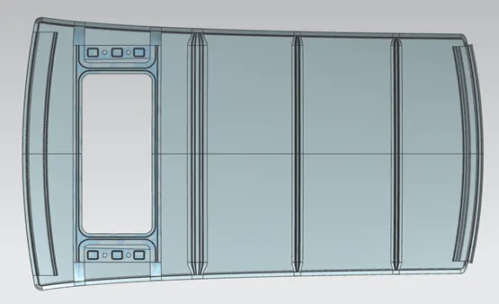
The inner panel and the bow roof are held up with mastic sealants throughout except the ends with are spot welded with the side flanges.
HEAT DISTORTION CRITERIA:
W = [1.73 x 10^(-3) x L] + [1.85 x 10^(-8) x (R^2)/t] + [ 1.10x10^(-3) x l] - 2.68
Judgement Condition: OK< 2.7> 3.1
Where
L = Roof Length in X-Direction[mm] (Roof dimension in 0-Y)
R = Roof curvature = 2(Rx*Ry)/(Rx+Ry)
Rx = X curvature
Ry = Y curvature
t = Roof plate thickness [mm]
l = Bow Roof Span [mm]
|
S.NO. |
BOWS |
Rx |
Ry |
R |
I |
L |
T |
R^2/T |
W |
OK/NG |
|
1 |
FR. TO CTR |
SUNROOF |
SUNROOF |
SUNROOF |
SUNROOF |
SUNROOF |
0.75 |
SUNROOF |
SUNROOF |
|
|
2 |
CTR TO 1BR |
4301.84 |
4301.84 |
4301.84 |
386 |
2026.52 |
0.75 |
24674436.51 |
1.706957 |
OK |
|
3 |
1BR TO 2BR |
3552.3 |
11274.15 |
5402.3941 |
400 |
2026.52 |
0.75 |
38914482.77 |
1.985798 |
OK |
|
4 |
2BR TO RR. |
3022.129 |
14631.34 |
5009.5306 |
275 |
2026.52 |
0.75 |
33460529.63 |
1.747399 |
OK |
Snow load Prediction formula
Qr = [Iy x t2] / [α x s x [(Rx + Ry)/2]2 x 10-8]
Note: The Qr value given over here is correct. There was a typo error in the formula given in the video.
Where
α = My x Lx2 x 10-12, My = Y(Ly-Y)
Judgement condition = Qr ≥ 3.1
250 ≤ s ≤ 380
t = Roof plate thickness [mm]
Ly = Distance between the front and rear roof Rails on the Vehicle along with 0Y[mm]
Length of Roof panel with the centre point between Roof rail Front /Rear as the reference point of the front and the rear.
Lx = Distance between the Left and Right end of the roof on the Roof BOW [mm]
Width of the roof panel exposed on the surface.
Y = Distance front Front Roof Rail to Roof BOW [mm]
s = Distance for which Roof BOW bears divided load [mm]
s = L1/2 + L2/2
Iy = Geometrical moment of inertia of Roof BOW (Y cross-section) [mm4]
Rx = Lateral direction curvature radius of roof panel Y cross-section on Roof BOW [mm]
Roof panel curvature Radius of the Length Lx in Front view
Ry = Longitudinal Direction curvature radius of the Roof panel X cross-section on Roof BOW [mm]
Roof panel X curvature radius of length s in Side view
|
SNO |
BOW |
Iy |
ALPHA |
Lx |
Ly |
Y |
S |
Rx |
Ry |
T |
Qr |
OK/NG |
|
1 |
FR TO CTR |
SUNROOF |
SUNROOF |
SUNROOF |
SUNROOF |
SUNROOF |
SUNROOF |
SUNROOF |
SUNROOF |
0.75 |
SUNROOF |
SUNROOF |
|
2 |
CTR TO BR1 |
354.3025 |
0.719549225 |
1065.9721 |
2026.52 |
386 |
225 |
4456.785 |
8098.969 |
0.75 |
3.12340363 |
OK |
|
3 |
BR1 TO BR2 |
64.55 |
0.713242263 |
1047.0293 |
2026.52 |
400 |
275 |
3869.1 |
12620.645 |
0.75 |
4.2321821 |
OK |
|
4 |
BR2 TO RR |
64.55 |
2026.52 |
275 |
0.75 |
#DIV/0! |
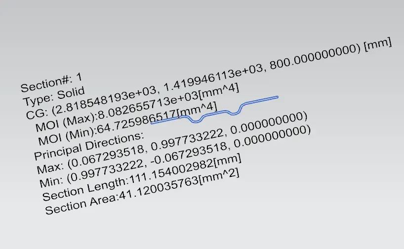
SECTION INERTIA :
CTR. ROOF RAIL
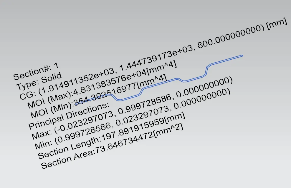
BOW ROOF 1
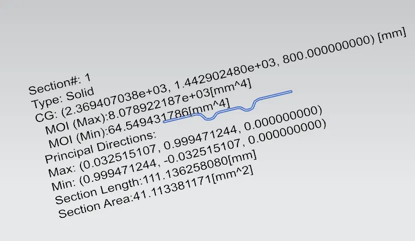
BOWROOF 2