Week 8 - Challenge 3 - Coin Holder Design
Aim
Create the Coin Holder Plastic component through the given Class-A surface. To begin with, the tooling axis for the given Class-A Surface should be created meeting the requirements of the draft angle and at the end perform the Draft analysis on the model.
Take the Thickness of the component to be 2.5 mm
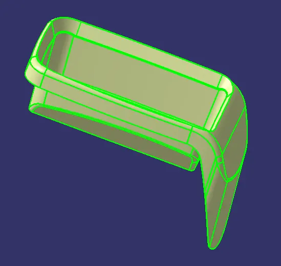
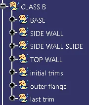
Procedure for creating the switch bezel
- Creat tooling axis
- Creat B class surface
- Creat C class surface
- creat closed surface
- Do draft analysis
Creat tooling axis
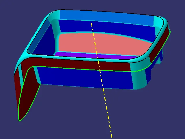
1.the tooling axis is created by Evaluating w.r.t X,Y,Z axis method (Y axis used)
2.The base surface of the class - A was extracted and a point at the centre is created
3.then use line commend to creat tooling axis in the y direction

Creat B class surface
1.In the case of Class A the surface below is called core and the surface above is called cavity.
2.Class A is an aesthetics surface and class B is an engineering surface.
3.B surface should be inside the class A surface.
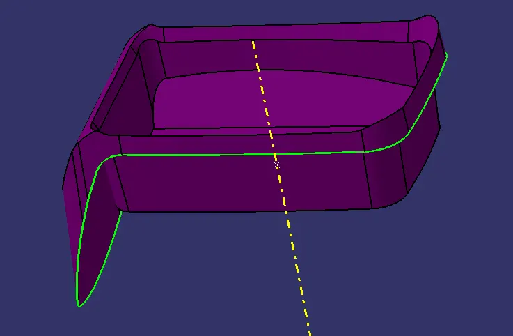
4.B surface can be divided into four surfaces the side walls, top walls, outer flange and the base surface and later trim them altogether.
5.First step is to create the side wall surfaces by extracting the required surface from Class A and untrimmed it thus we will get a single surface which will be extrapolated to get the required size and finally offset it to the inner side of class A as per the thickness of the material and trim them together and apply the required fillet by measuring the values from class A.
6.Base surface of the component is then extract, untrimmed, extrapolated, offset and trimmed.
7.The top walls can be directly extrapolated from the extracted surfaces and offset it for the required size of the material.
8.Then join the base, side wall and top wall by trim operations.
9.As the Outer flange is surface complex it can be divided into two parts and extract them then go for extrapolation, offset, split and join operations and finally check the for the connectivity by intersecting method.
10.Now all the four geometries are trimmed together to get the B surface.
11.Fillet is applied to the required surfaces by measuring the fillet value from the class A surface
Creat C class surface
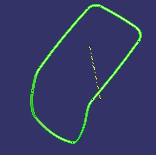
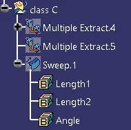
1.C surface has been created from the boundary lines of class A surface and by extracting the supporting surfaces then sweep the boundary lines with reference to the extracted surfaces.
2.In order to get the C surface first we have to create a boundary lines of class A surface or by using multiple extrapolated command and check for the continuity of it.
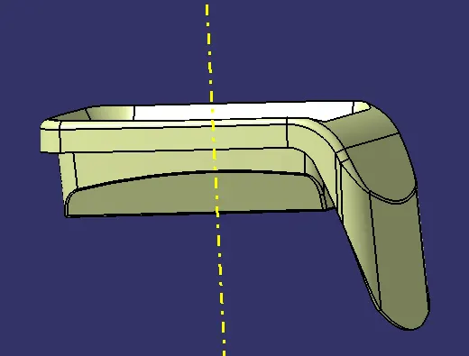
3.Create a sweep with reference to the curve and the reference surface with a 90 degree angle and give the inside direction Check for the continuity of the surfaces if there is any gap go for extrapolated and trim all together now we will get the class C surface.
creat closed surface
1.Then trimmed the class c surface and b surfaces together by join command then check it for connectivity of the surfaces if it is ok then finally join it with A surface we will get the final component again check whether the final body is closed by using boundary command.
2.Closed solid body is created by using the close surface on part workbench by selecting the final join component and do the draft analysis for the same.
Do draft analysis
1.First the class - A surface is checked before creating the Class - B & C surface and finally the solid body must be analysed . Both can be done by following the below procedures.
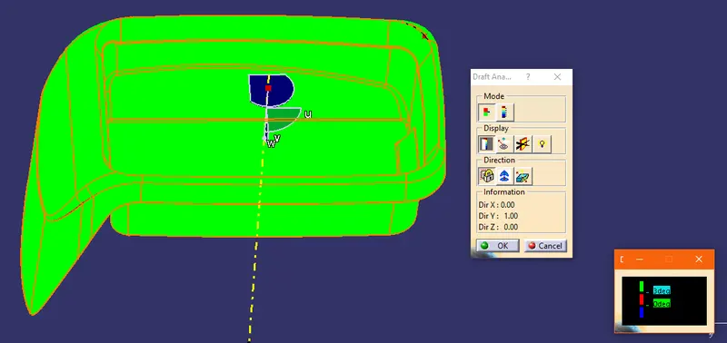
2.By changing the view mode to custom view parameters - Material mode then the feature draft analysis is enabled.
3.Then the compass was activated and placed with the tooling axis by dragging the redpointer and then lockes it
4.Then, by selecting the quick analysis mode, the nominal value will be 3 degrees and checked for the component's draft angle
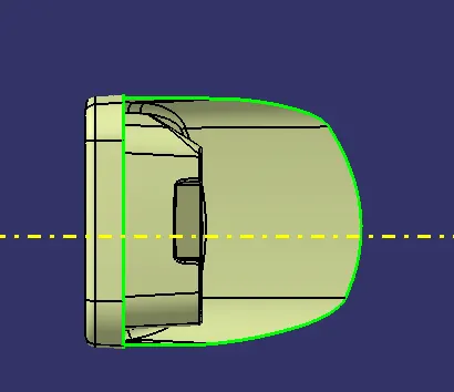
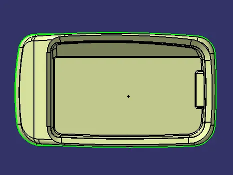
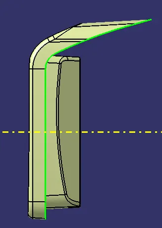
5.The green colour area shows that it satisfies the 3 degree draft angle.
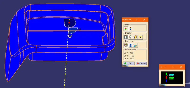
draft analysis on class A surface
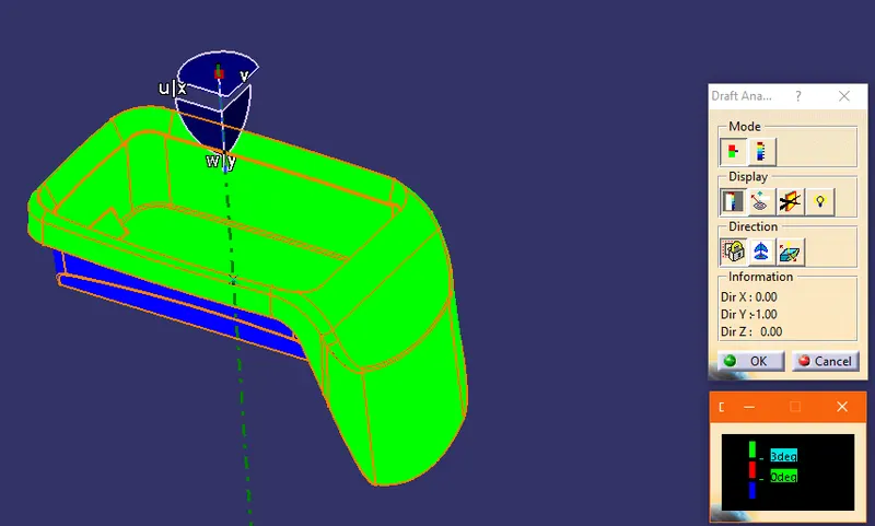
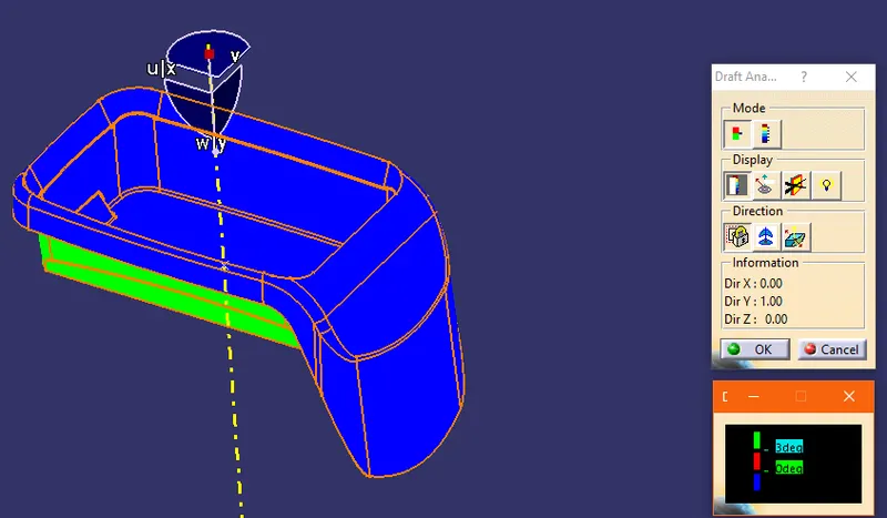
draft analysis on final surface
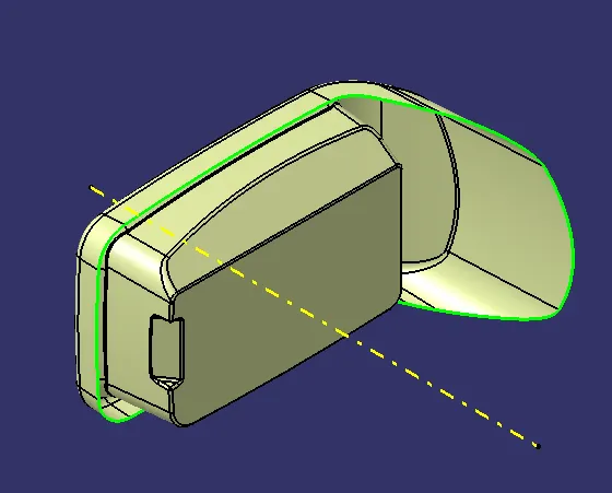
Isometric, Front, Side, and Top View
Conclusion
Finally i done the coin holder Plastic component through the given Class-A surface. To begin with, the tooling axis for the given Class-A Surface should be created meeting the requirements of the draft angle and at the end perform the Draft analysis on the model.Take the Thickness of the component to be 2.5 mm