Week 8 - Challenge 3 - Coin Holder Design
COIN HOLDER DESIGN
AIM
To create the Coin Holder Plastic component through the given Class-A surface.
OBJECTIVE :
To make sure that the model meets the requirements of the draft angle.
To create the Tooling axis using bisecting method.
To perform Draft analysis on the given Class A Surface.
To create the required Class B and Class C surfaces.
To obtain a solid body from the surface using Close Surface feature.
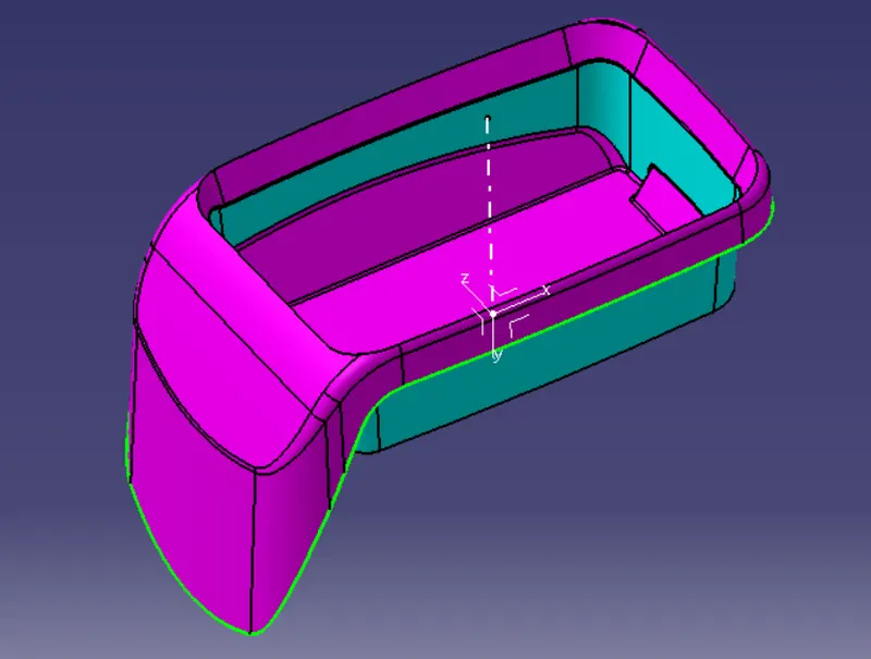
CLASS A SURFACE :
Class A surfaces are those surfaces which are curvature continuous while providing the simplest mathematical representation needed for the
desired shape and does not have any undesirable waviness.
The Class A surface is the used to begin the design of a product.
All the further intricacies of the component are created based on the Class A surface
CLASS B SURFACE
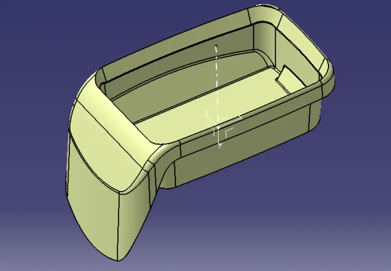
The Class B surface is created from the Class A surface , keeping the thickness of the component in check.
The Class B surface resembles an offsetted surface from the Class A.
CLASS C SURFACE
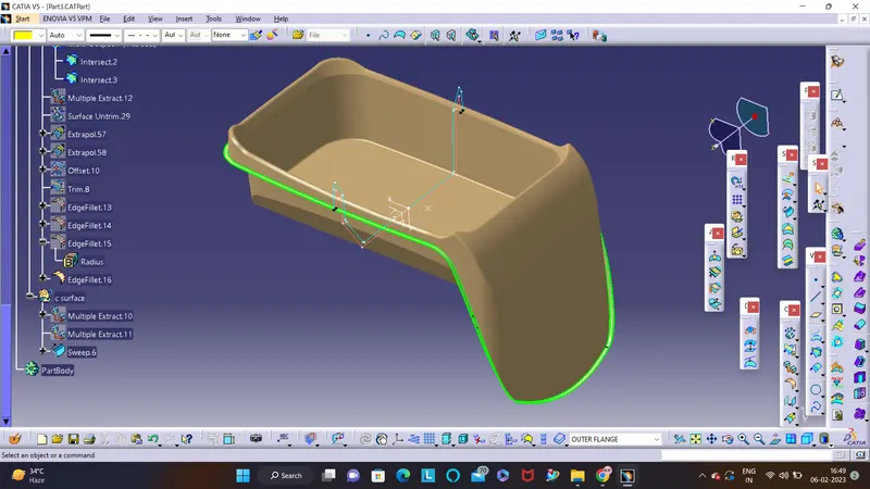
The Class C surface is used to bind the Class A and Class B surface together inorder to form a closed surface.
PROCEDURE
CREATING TOOLING AXIS
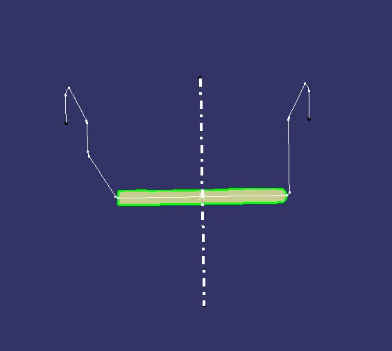
Initially a base surface was extracted from the Class A to create a center point.
An axis system was created upon this point.
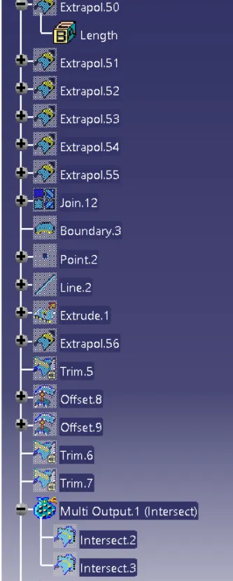
The Intersect feature was used to obtain a boundary of the Class A intersecting at the mid plane.
Once the check for the discrepencies in the boundary is done, the Tooling axis was created from thr mid-point.
CREATING CLASS B SURFACE
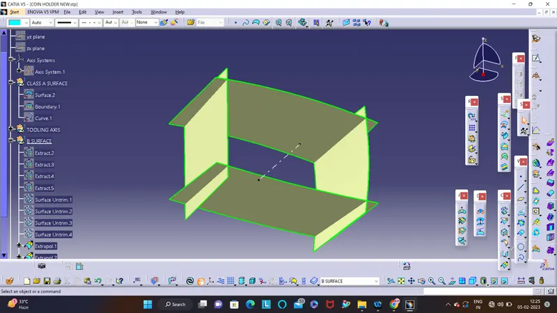
The Class B surface was formed from four diffrent segments of surfaces.
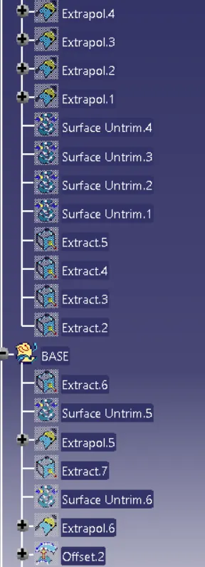
The required surfaces were obtained from the Class A surface using Extract command.
These surfaces were further expanded using Untrim and Extrapolate commands.
The protuding surfaces were trimmed using the Trim command and a proper continuous surface was obtained.
The same procedure was followed for all four segments.
The necessary fillets were added to the Class B.
CREATING CLASS C SURFACE
The Class C surface is used to bind the Class A and Class B surface together inorder to form a closed surface.
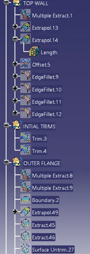
The Outer flange of the Class B was used in the Class C creation.
It's outer boundary was extracted.
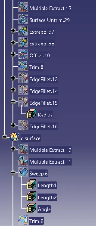
The Sweep surface feature was used along with With reference surface option , selction the curve and the surface which was extraced earlier.
The angle was entered as 90 degree so that the surface protudes outside therfore intersecting the A surface.
The Hole present in the surface was also extened outside using the above steps.
CREATING SOLID BODY
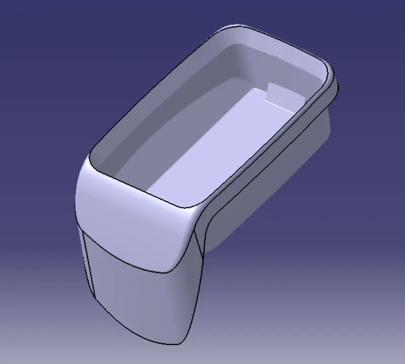
Finally the Class A, B and C surfaces along with the hole were trimmed together to form a closed surface.
Using the surface created the solid component was obtained using the Close surface feature present in the part workbench.
The Tooling axis, Class A, B and C surfaces were published.
DRAFT ANALYSIS
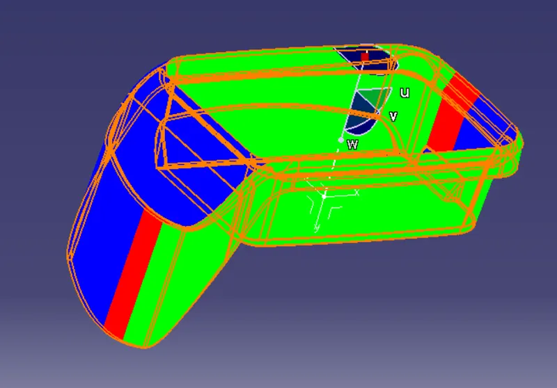
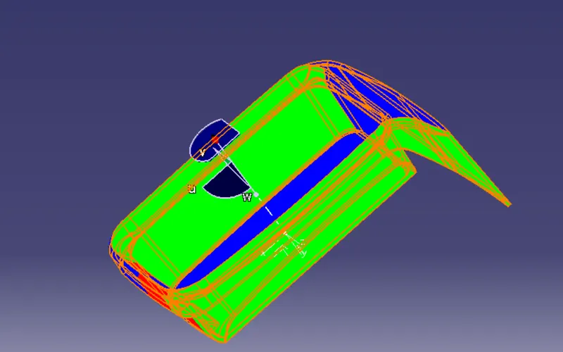
The Drafting analysis was performed using the Feature Draft Analysis command.
Using this command the compass was set on the main tooling axis and the Draft angle was changed to 3 degree.
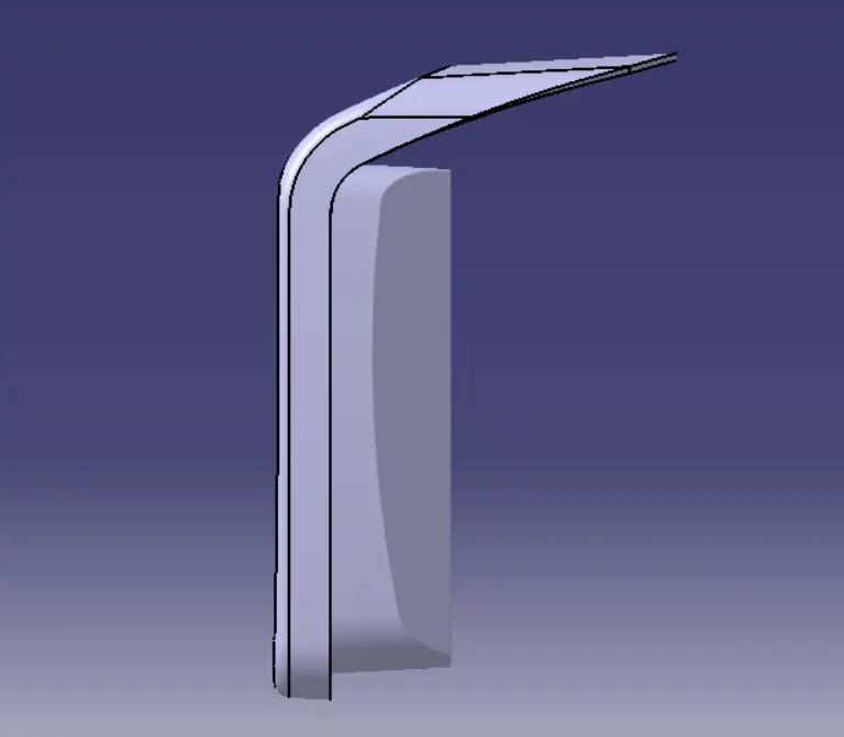
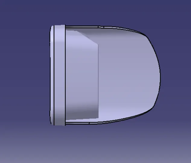
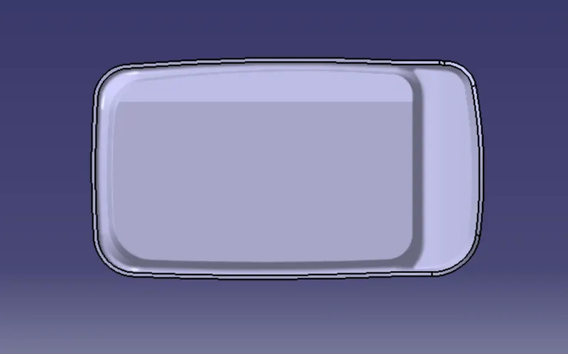
VIEWS OF SOLID BODY
ISOMETRIC VIEW
TOP VIEW
FRONT VIEW
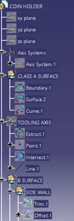
SIDE VIEW
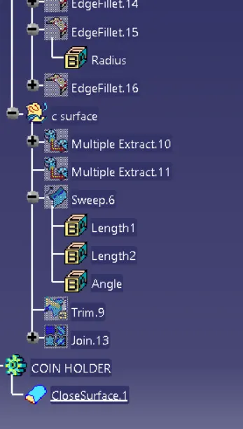
TREE STRUCTURE
CONCLUSION
To make sure that the model meets the requirements of the draft angle.To create the Tooling axis using bisecting method.To perform Draft analysis on the given Class A Surface.To create the required Class B and Class C surfaces.To obtain a solid body from the surface using Close Surface feature.The objective is done completly