Week 8 - Challenge 3 - Coin Holder Design
Creating the tooling axis:
The tooling direction is used to find the direction in which the part is ejected out of the mould or it is the direction in which the core and cavity are moved and the part is ejected.
The draft on the part should be positive in order to manufacture the part easily. The draft angle should be positive with respect to the tooling direction.
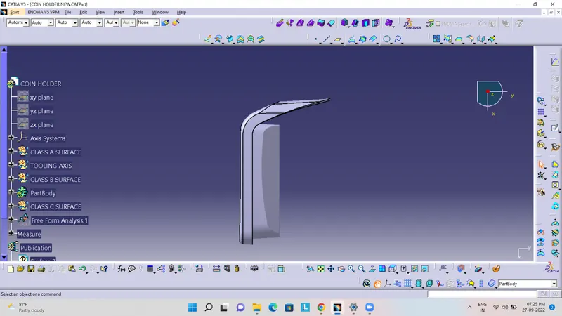
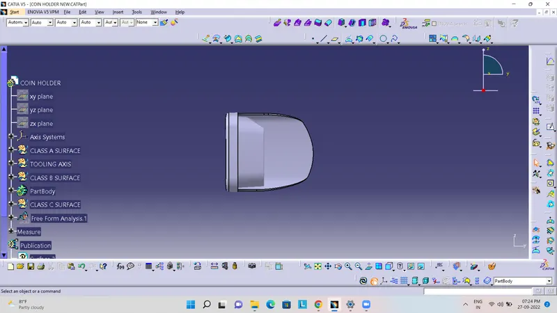
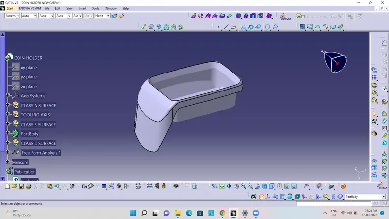
To create the tooling axis, we need the proper orientation or view that gives the correct features and draft available in the component. So here the component view from the Y-direction gives the proper view for the tool to see the features present in the geometry.
To create the tooling axis from the Y direction we need the tooling axis from the other direction that gives the wall draft angle.
The bin base centre will be the initial tooling axis for the coin holder.
The tooling axis created by following steps
- The base surface is extracted
- Then the centre point is created using the point > on the surface at 0
- At the point created the axis system is created.
After that switching the view of the model to the X direction and creating the tooling axis.
Using the intersect in the ZY plane to get the boundary lines. Then the lines are created along the slant surfaces.
Here the wall lines form the zero degrees angle with the base. So, the final tooling axis will be perpendicular to the base or in the Y direction from the centre point.
Draft analysis:
To perform the draft analysis the view parameters are first set to material mode.
Then go to Insert >>analysis>>feature draft analysis.
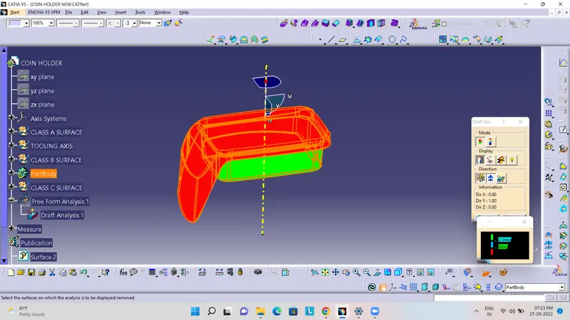
First, select the axis system and drag the axis system to align and coincide with the tooling axis and lock the orientation. This axis system defines the draft direction according to the tooling axis.
Switch on the colour scale and set the minimum draft value. Here it is set to 3 degrees and it will be displayed in green colour. Any draft angle below 0 degrees will be shown in red colour.
Now select the running point tool to measure the draft angle at the various locations and then if all surface passes the draft analysis switch on the light effect that will show the component in green colour if the component has the required draft angle. The final draft analysis shows the green colour surface having the draft angle above 3 degrees and red or cyan colour shows the draft angle below 0 degrees.
All the surfaces with green can be easily manufactured with the injection moulding but the red colour surface which is a negative draft cannot be ejected or manufactured with the main tooling axis.
The solution for this is to have another tooling axis that captures all the rest surfaces but this is not feasible or the last option to make changes in the A-class surface.