Week 8 - Challenge 3 - Coin Holder Design
Coin Holder Design
Aim
Create the Coin Holder Plastic component through the given Class-A surface. To begin with, the tooling axis for the given Class-A Surface should be created meeting the requirements of the draft angle and at the end perform the Draft analysis on the model.
Objective
To Design a coin holder in CATIA V5 using the given Class A surface and design parameters.
Input data
We use class-A- surface as an input data.
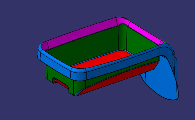
Tooling direction
Tooling direction in which 2 halves of the mold get separated against each other. for this model am going to use the normal-to-face method instead of bisecting method because the sidewalls of the class A surface was in 90 degree so i choose normal to face option, my tooling axis will be on the Y axis because in the Y direction only we have a flatter surface and one more thing is there are no possibilities to manufacture this component in X&Y direction .
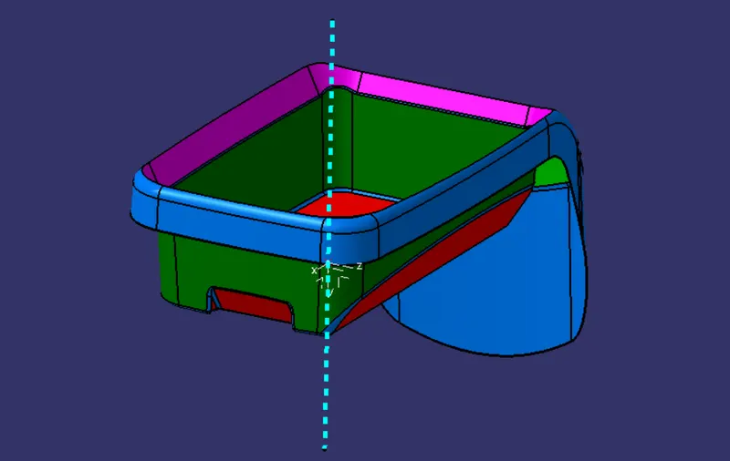
B-Surface creation
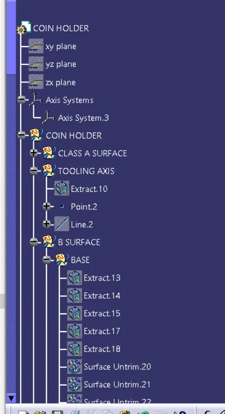
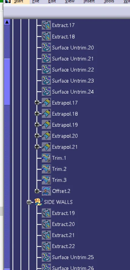
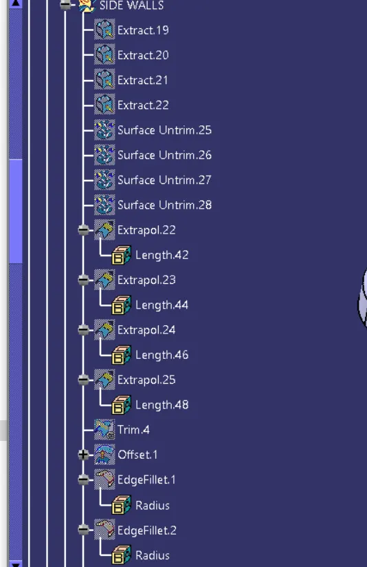
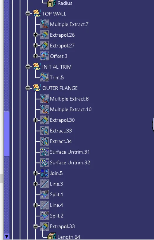
As usual B surface is created using the standard procedure by extract, un trim, extrapolate, join, Trim, split,fillets and offset commands. The B-surface is created parallel to the A-surface.
Note: The Thickness of the component is 2.5 mm
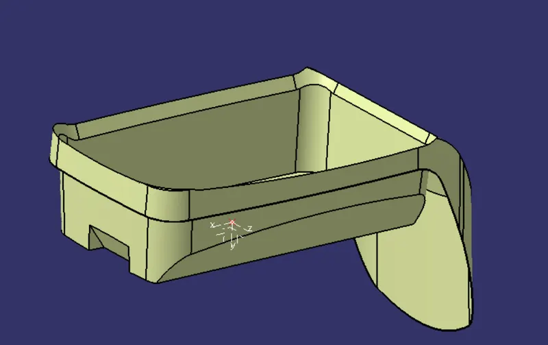
C-Surface creation
Class C surface for this component is created using the sweep command. All the ends of the component surface were facing downwards, so the C surface will create perpendicular to B surface.
To create a C-surface we need to extract the boundary of the A surface by using the multiple extract command then create a swept it is perpendicular to the class-A-Surface outer edges.
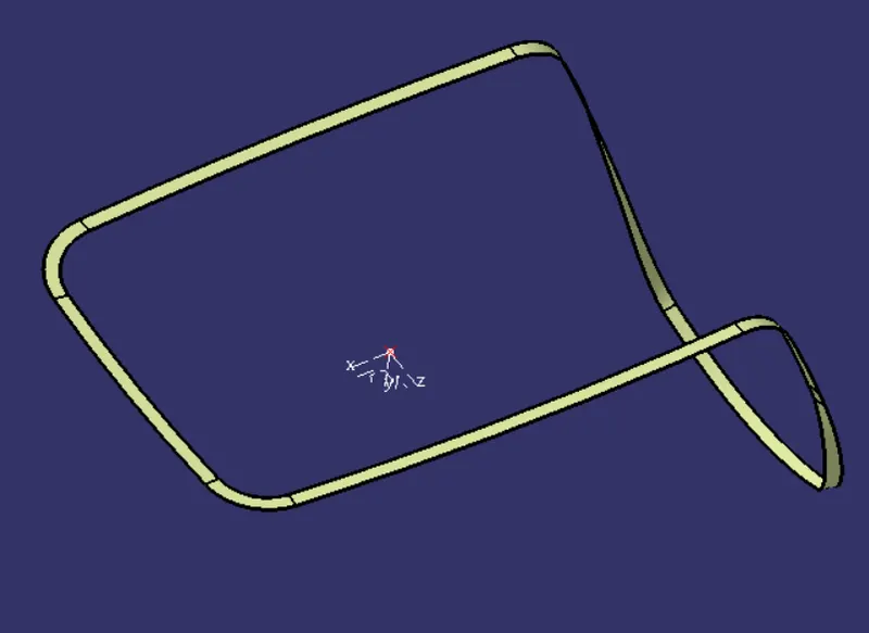
Features used
- Extract
- Offset
- Trim
- Untrim
- Split
- Swept
- Fillet
- Multiple extract
- Join
- Extrapolate
Feature tree
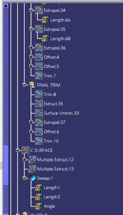
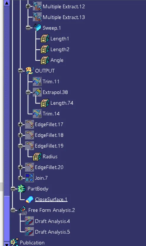
Different views
Front view
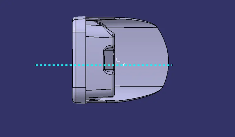
Right view
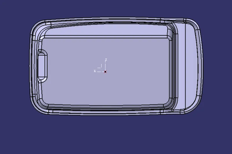
Top view
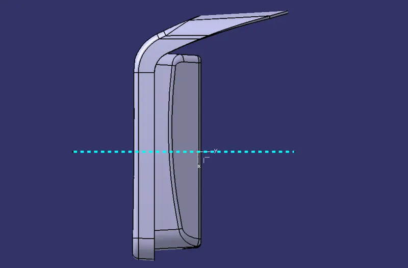
Isometric view
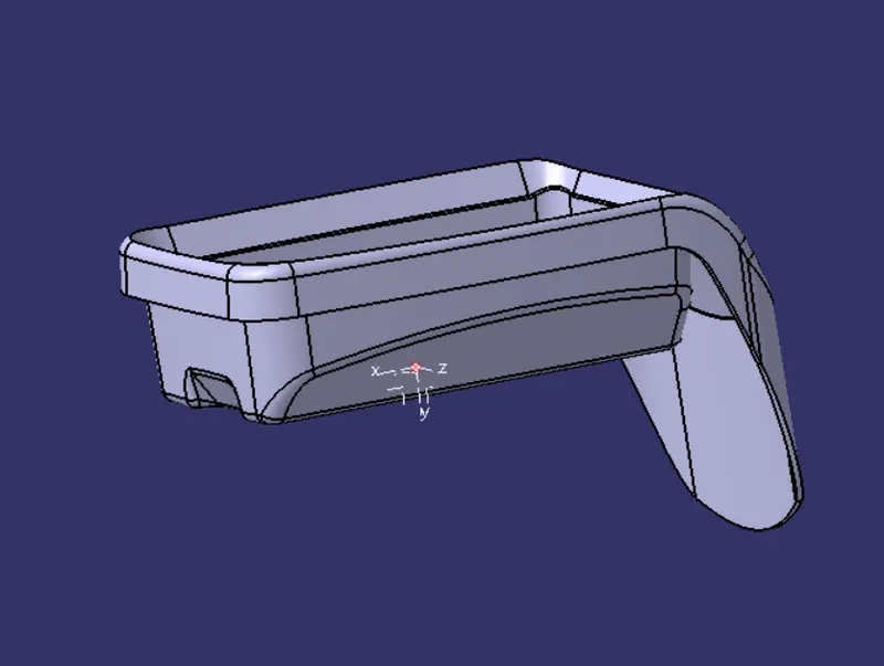
Converting into the solid model
Once all surfaces are created Class A, B, and C surfaces are joined together to get the final closed volume. The closed volume is then converted into a solid body using the closed volume command in the part design workbench
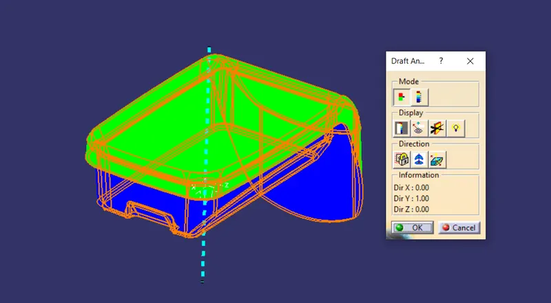
Draft Analysis
The Draft Analysis allows the user to easily analyze a part for a proper draft angle and check to the manufacturability of the component.( In this case this model will be hard to manufacture because side wall of this component was not clearing the minimum draft angle of 3 degree)
Conclusion
I have successfully completed the Coin holder challenge by using CATIA V5