Week 8 - Challenge 3 - Coin Holder Design
COIN HOLDER DRAFT ANALYSIS REPORT.
STEP 1.
Examination of class A
STEP 1:- using boundry command checked for any non intersecting surfaces, if found any should be done using appropriate commands, but in this case class A was all good.
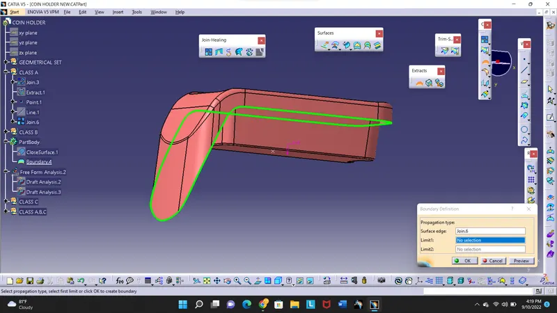
STEP 2:- using join command for creating single surface to work on, for reference for CLASS B , CLASS C .
STEP 2.
Draft analysis of class A,
STEP 1 :-
CREATION OF TOOLING AXSIS
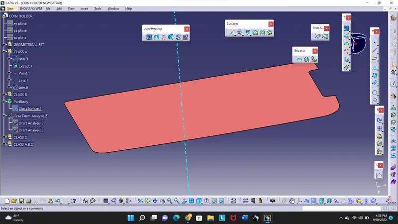
extract any surface of class A as shown in fig.
creat point on surface , and then take line normal to surface , actual tooling axsis should be normal to surface only because most of machinery available have only vreticle tooling axsis and horizontal axsis tooling direction.
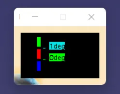
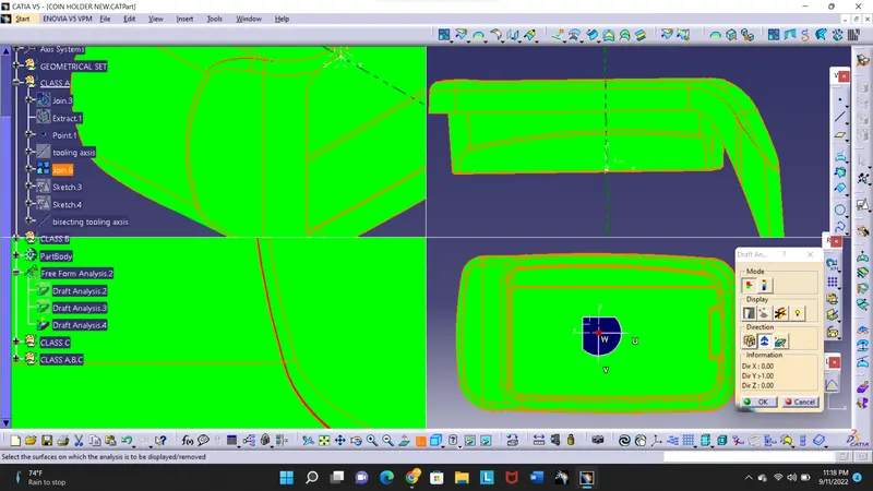
STEP 2:- insert draft analysis , place compass on tooling axsis and define the direction, and again place compass on tooling axsis and click on surface, following fig explains the process.
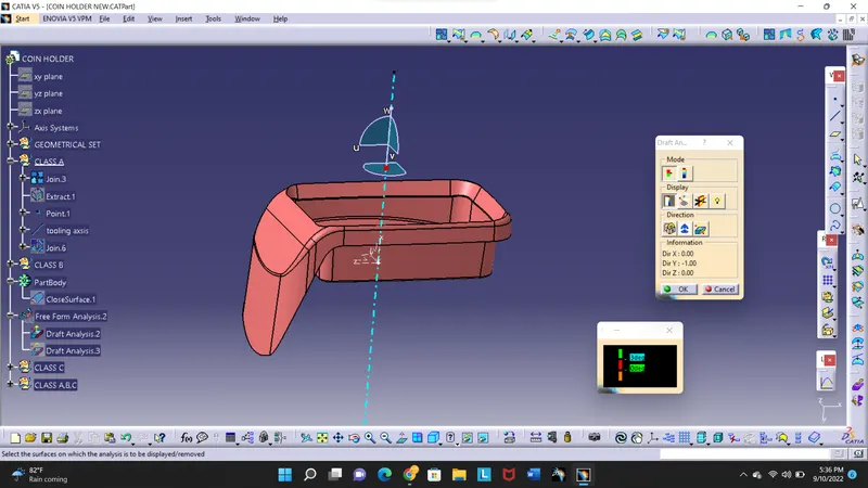
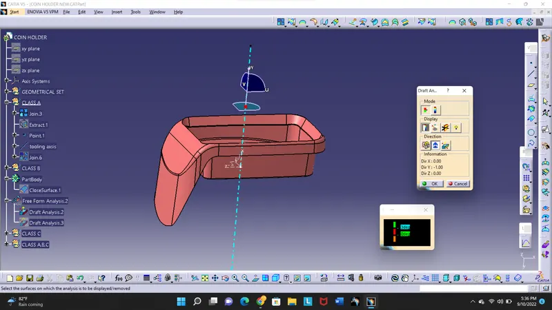
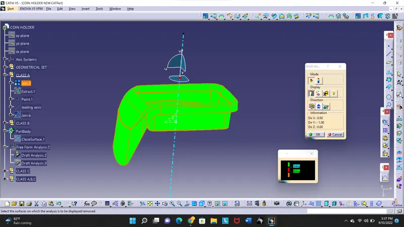
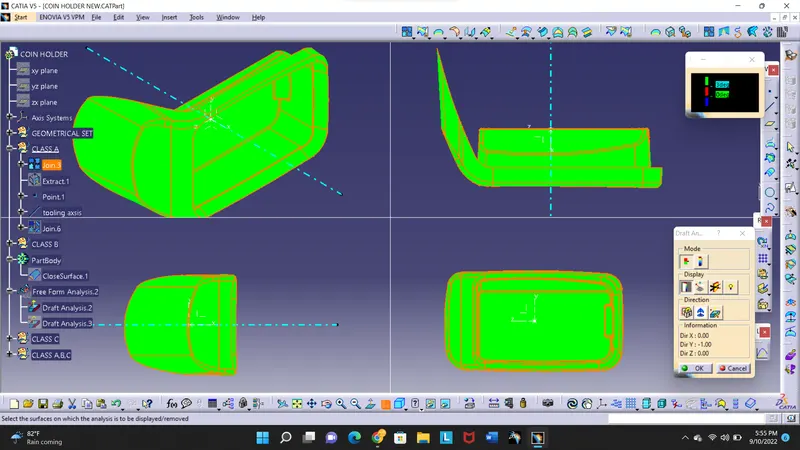
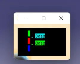
STEP 3:- analyse the componant clearing the draft analysis or not,
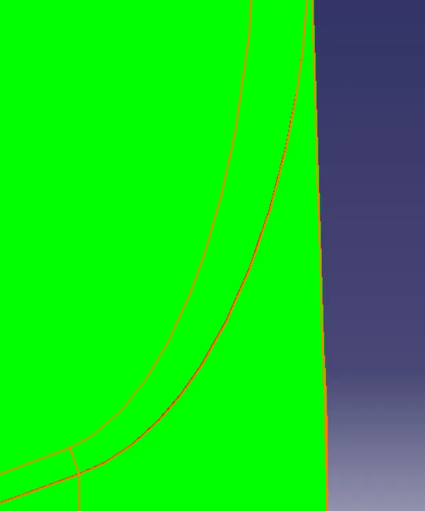
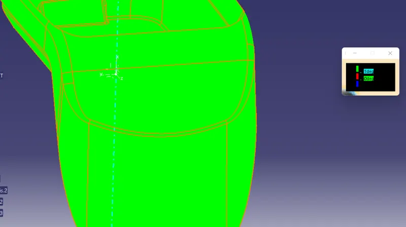
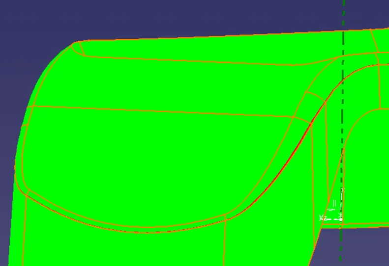
in given class A green colour shows positive angle of draft analysis and red colour shows negative draft angle ,
in given class A surface, some part shows negative angle (red coloure ) shown in fig.
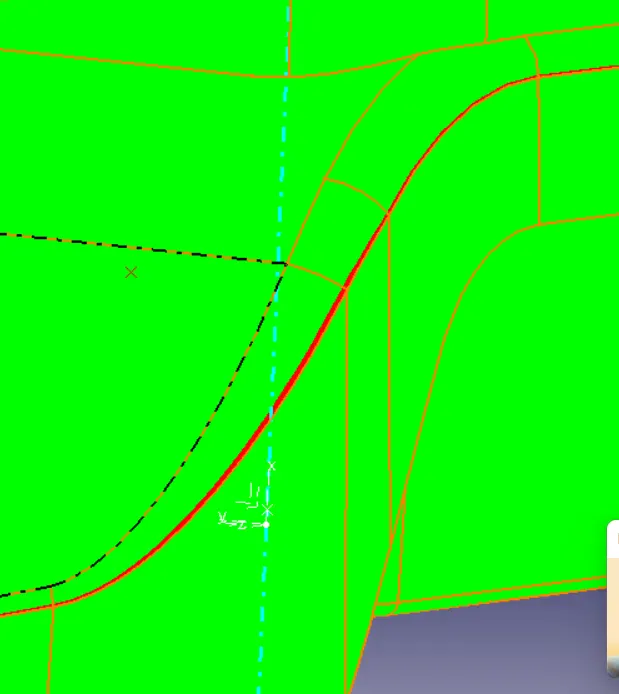
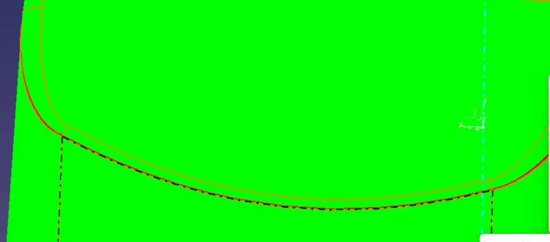
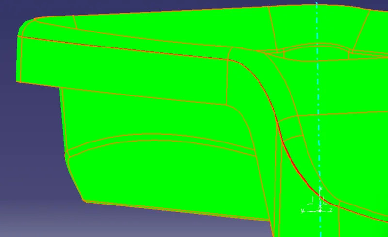
some part of given class A surface did not cleared draft analysis,
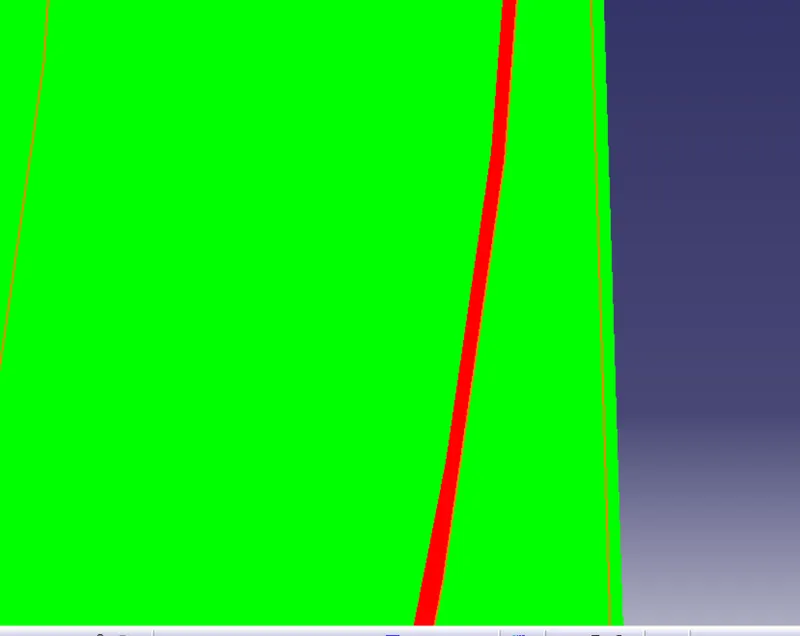
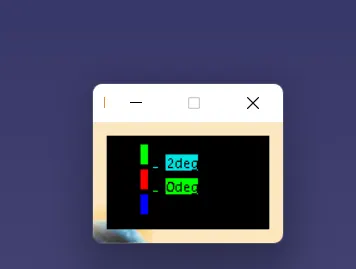
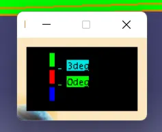
itrations tried from 3 degree angle to 0.5 degree angle ,
shown in fig.
STEP 4:-
CREATION OF BISECTING TOOLING AXSIS,
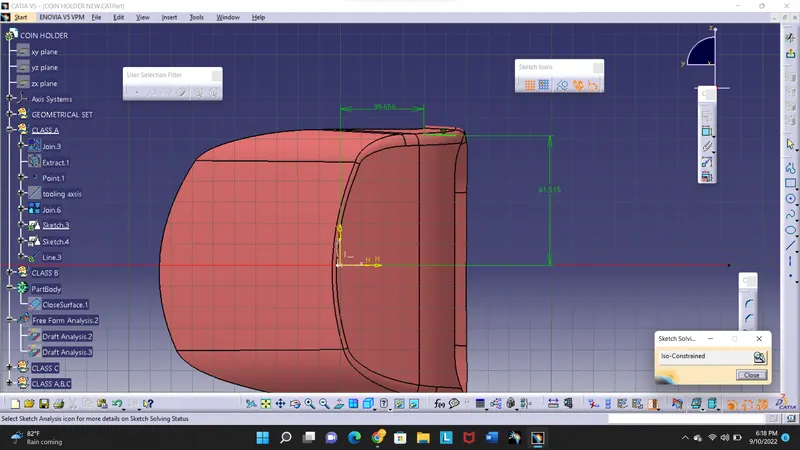
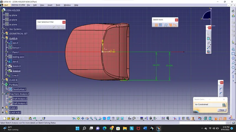
projecting two lines and creating bisecting line
STEP 5:-
DRAFT ANALYSIS ON BISECTING TOOLING AXSIS
same result appered on bisecting tooling axsis
some part shows negative angle as shown in fig below.
this may also apper in final product also ,
STEP3.
CREATION OF CLASS B,
STEP 1:- LOWER BODY
extracting the required surface from class A ,as showen in fig.
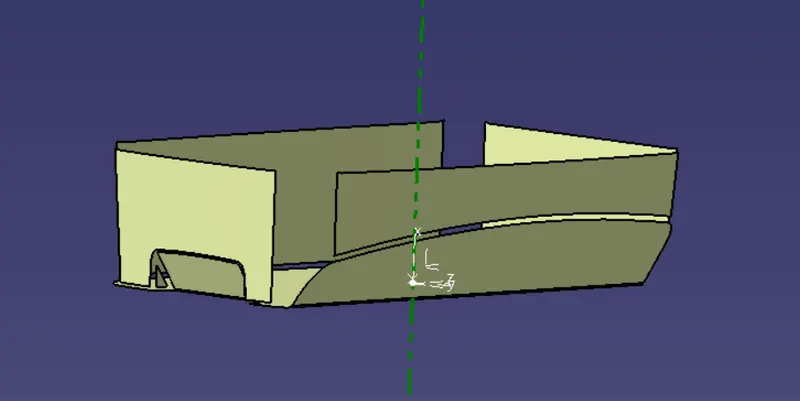
STEP 2:- un triming and and ofseting surfaces by 2.5mm, join and extrapolateing further shown in fig.
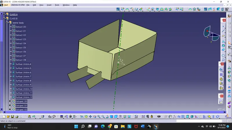
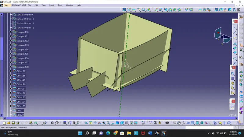
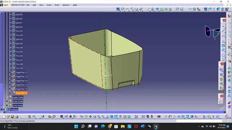
STEP 2 :- triming outre body with inner body and then with lower body ,
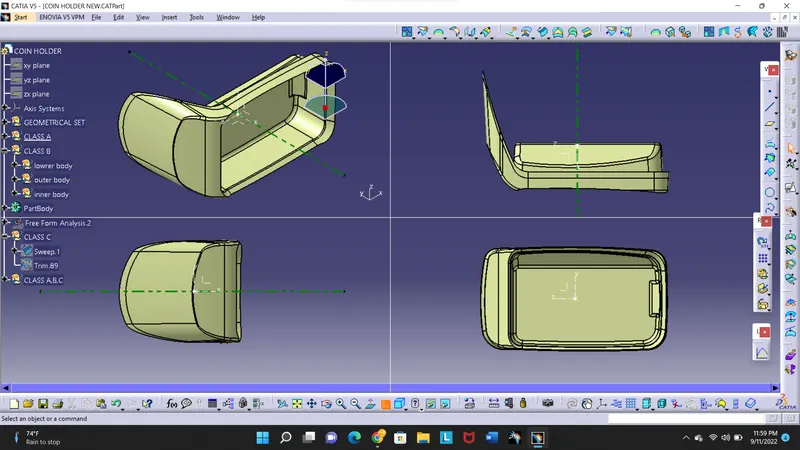
and exteapolate final class b as shown,
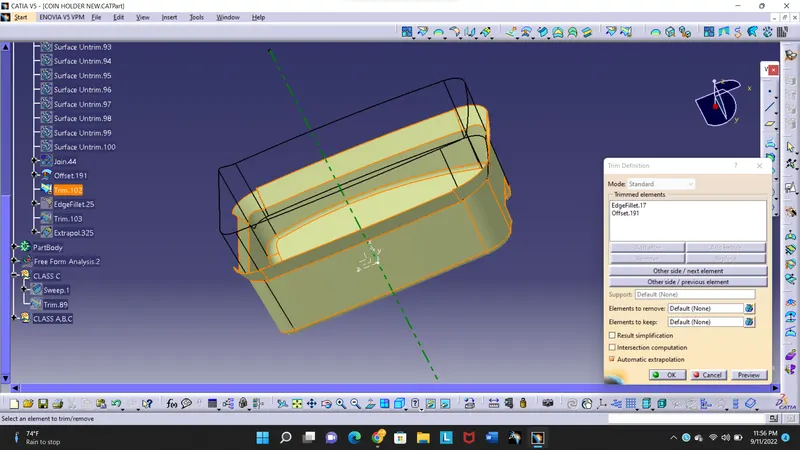
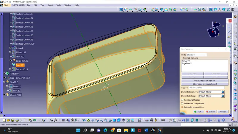
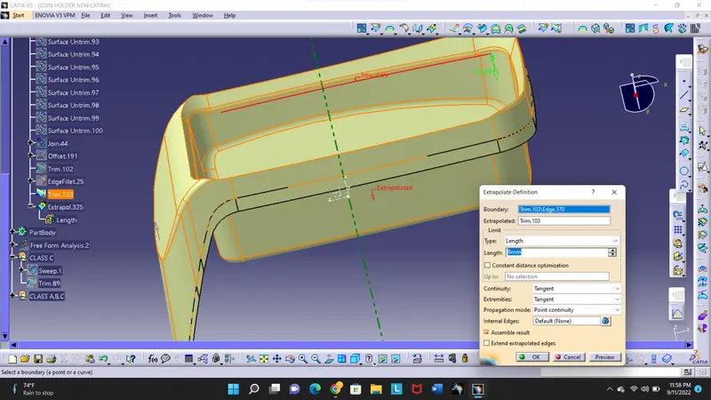
final class b all views ,
STEP4.
CREATION OF CLASS C AND CLASS A,C
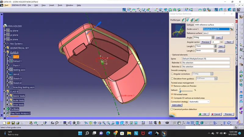
STEP 1:- class C is created with given class A, by using swep command as shown in below fig.
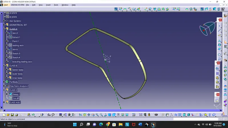
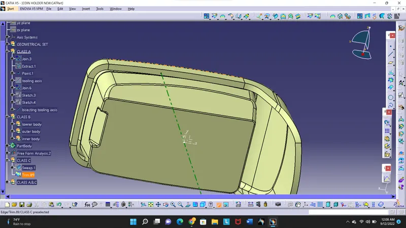
STEP 2:- joinin class A and created swep with join command to creat class A,C
STEP5.
CREATION OF FINAL COMPONANT
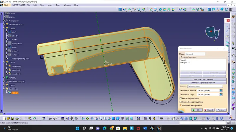
triming class A,C with class B using trim command,
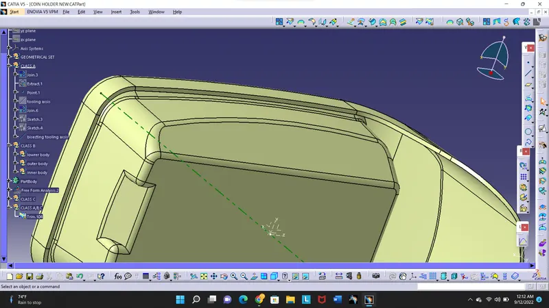
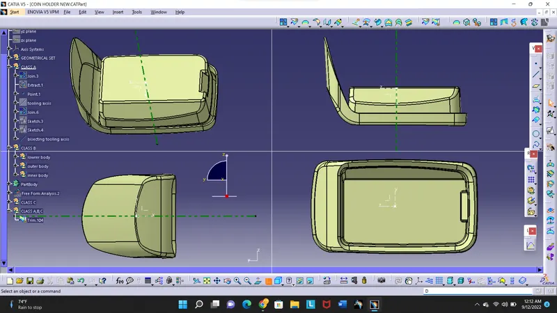
TREE STRUCTURE:-
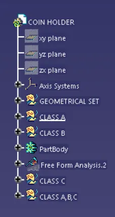
STEP6.
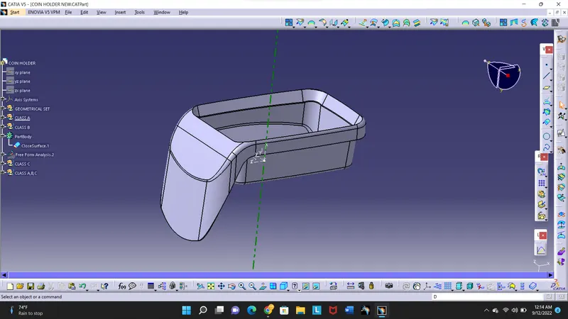
STEP 1:- CREATING FINAL SOLID COMPONANT USING CLOSED BODY METHOD.
STEP 2:-
DRAFT ANALYSIS OF FINAL COMPONANT,
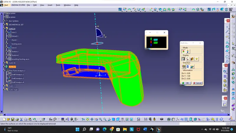
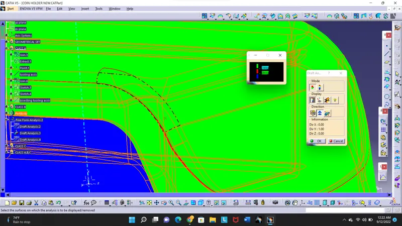
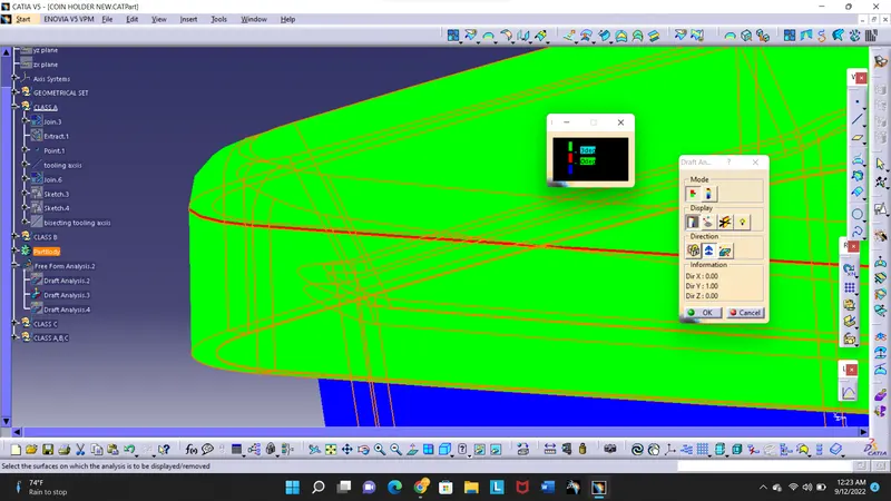
3 degree of draft angle on normal tooling axsis shows some edge as negative draft as mentioned in class A draft analysis report ,result is as shown in below fig.
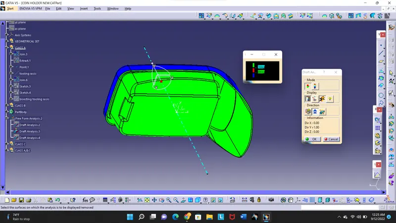
INVERSING DRAFT DIRECTION RESULTS ARE AS SHOWN,
in this we can see bottom part of componant clearing draft analysis
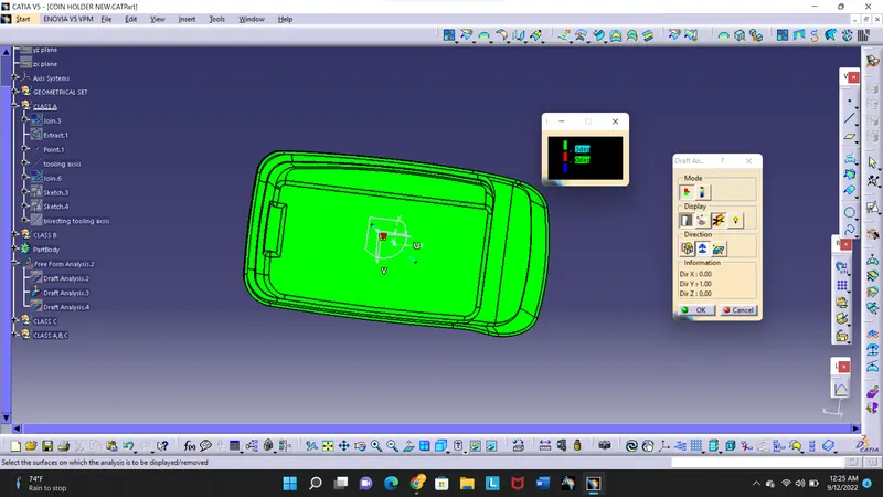
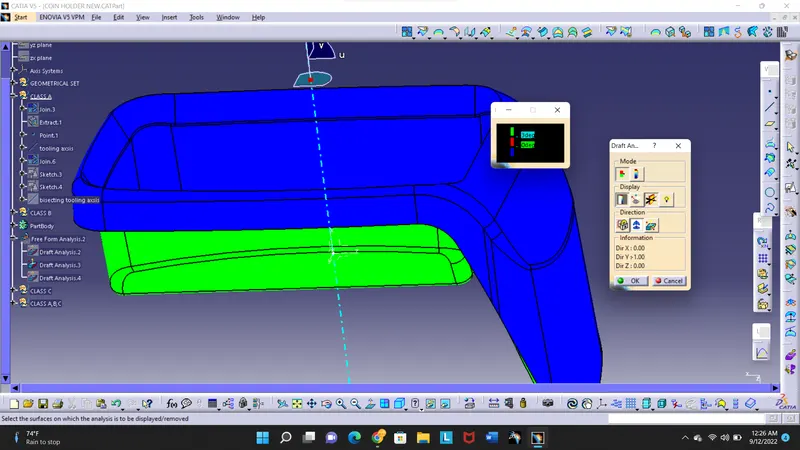
#NOTE:- AS SAME RESULT APPERED WITH BISECTING TOOLING AXSIS ONLY NATURAL TOOLING AXSIS RESULTS ARE SHOWN,
FOR DRAFT ANALYSIS OF FINAL COMPONANT.