Week 8 - Challenge 2 - Switch Bezel Design
Aim: -
Create the Switch Bezel Plastic component through the given Class-A surface.
Objectives:-
- To create class B & C surface for the given component.
- To form the tooling axis and capture the surface properly.
- To check the feasibility of the component with a draft of 3 degrees.
DRAFT:-
Draft angle is nothing but providing some tapered portion to the part for easy removal of the component from the mold during manufacturing. This is especially done in the case of plastic component design having a complex shape. Mostly the 3-degree draft angle is provided but it can vary depending upon the component which is to be designed
In our case of Switch Bezel design, the draft angle is 3 degrees the draft analysis is done during the design of the component to check the feasibility of the product.
Before providing a draft angle we need to decide on the tooling axis also known as the molding axis considering the faces which can cause issues while manufacturing.
TOOLING AXIS :-
It is nothing but the direction in which the mold opens and closes the draft angle needed to be provided by considering this tooling axis.
We can create a tooling axis by using the bisecting method.
BISECTING METHOD:-
This method is used for the generation of the tooling axis for that purpose first we need to decide the direction of molding and then we create one dummy tooling axis for the reference to the purpose.
In this method, we select the surfaces which can create problems and take intersections in the x and y-direction. By using these curves we draw two lines and then draw a bisecting line from these two lines in the x-direction and y-direction.
If it is done in x-direction then it is called a tooling axis clearing x-direction and if in y then tooling axis clearing y-direction.
After completing this we need to draw a final line bisecting this two tooling axis in the X and Y directions to get our final output.
Method:-
In order to obtain the proper draft analysis tooling axis is required and the following steps show how it is done.
As this component has 1 hole from where the tooling axis can be generated, however it does not have proper 4 walls to generate it. In this case, an approximation is made in order to obtain the tooling axis.
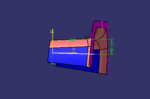
First by using the two side walls a dummy axis is made. As it is known that the draft angle is 3 degrees, the second axis is taken as a 3 degrees to the given wall and using these two axis the tooling axis is made.
Class A Surface:-
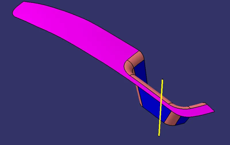
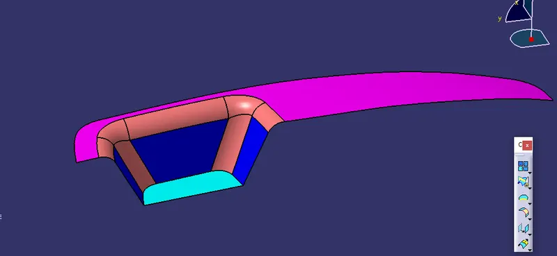
Using the two side walls 1st axis is made:-
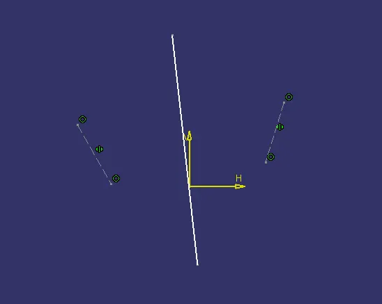
As the 4th wall is not there, an assumption is made and the axis is taken which is 3 degrees from the horizontal axis.
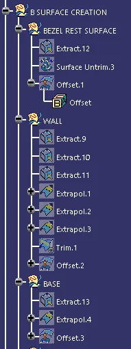
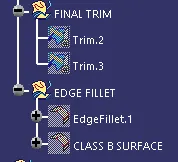
Class B Surface:-
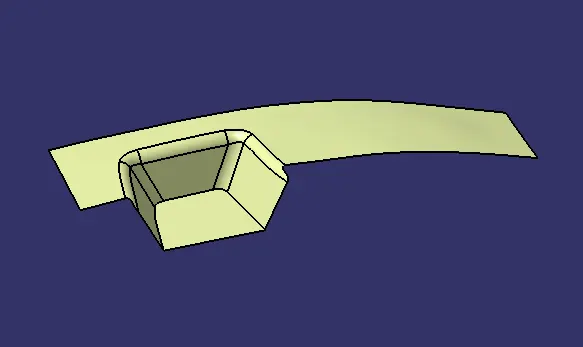
As per the requirement, the fillets are given. In order to given the fillets it is not exactly equal to class A. Along with the fillet radius, part thickness has to be added.
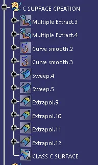
Class C Surface:-
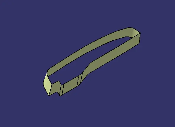
To capture class C surface it is necessary to sweep it to the required length. However for this as the border formed is having number of small sections the border curve can be smoothened and then swept or else done in parts.
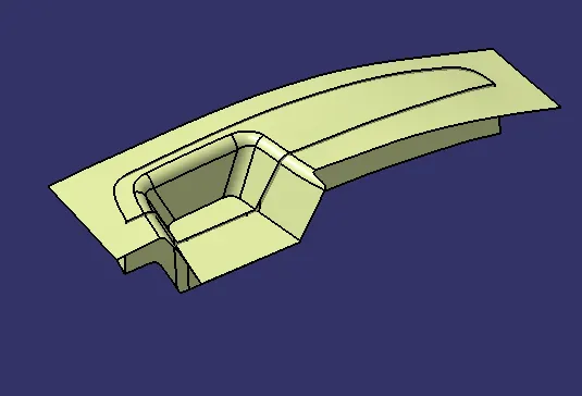
After forming the class b & C all the three surfaces can be trimmed and check for any discontinuity.
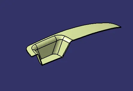
After trimming, this is how the surface will look like.
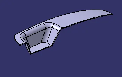
Solid formed after the class A,B & C surface.
Draft analysis:-
Isometric View:-
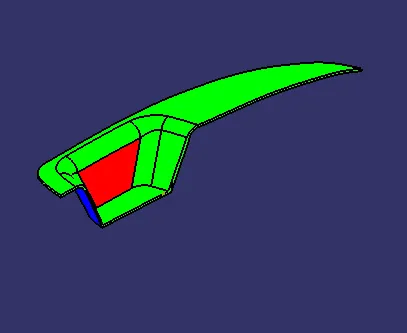
Top View:-
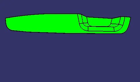
Front View:-
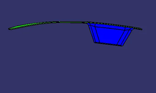
Side View:-
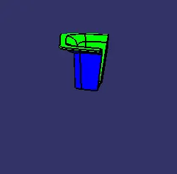
Class A surface draft analysis:-
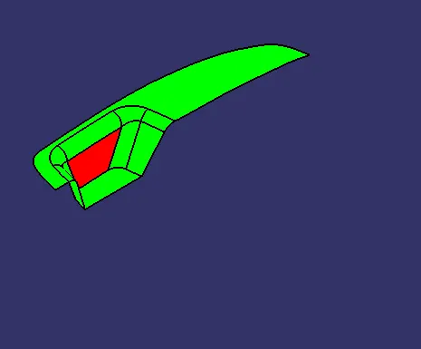
Solid Body:-
Isometric View:-
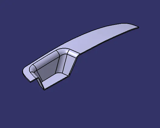
Top View:-
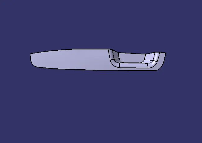
Front View:-
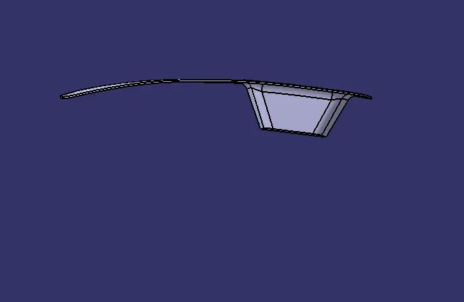
Side View:-
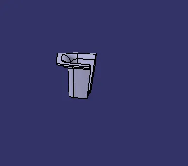
Expanded Tree Structure:-
Tooling direction:-
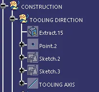
Class B Surface:-
Class C Surface:-
Class A,B&C Surfaces:-