Week 8 - Challenge 2 - Switch Bezel Design
Switch Bezel Design
Create the Switch Bezel Plastic component through the given Class-A surface. To begin with, the tooling axis for the given Class-A Surface should be created meeting the requirements of the draft angle and at the end perform the Draft analysis on the model.
Take the Thickness of the component to be 2.5 mm
Objective:-
Class A surface:-
Main objective of this challange create the Switch Bezel of the Plastic component throughout given Class A surface and by given tooling axis and Draft analysis to make Class A - surface to thickness to solid body
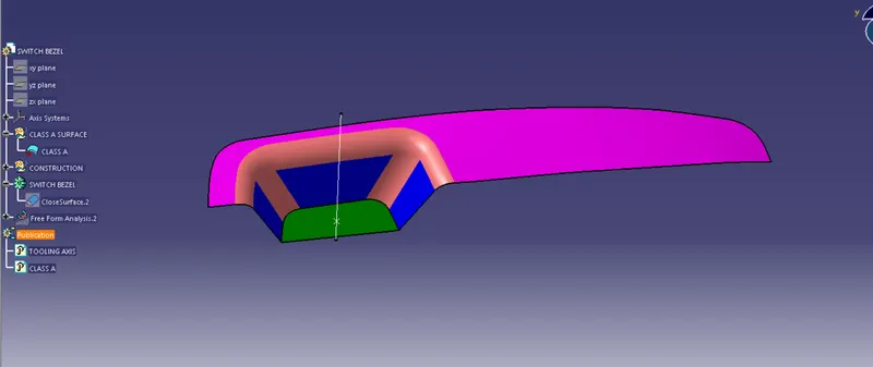
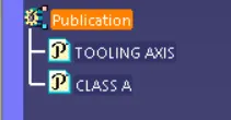
Tooling axis of Class A - surface:-
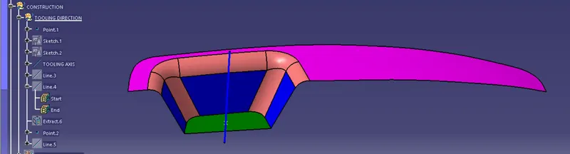
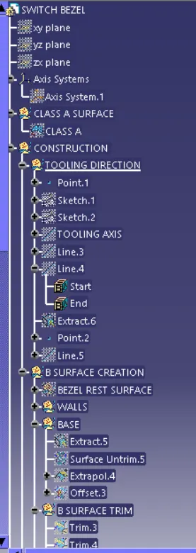
Class B surface creation:-
Class A surface extract to the above the arm rest and extract at it , and Untrim

- Class A suraface wall all are into untrim and Exterpolated
- Base wall also untrim and exterpolated and are base surface and side wall are to be untrim , offset the remaing surface 2.5mm Distannce
- Finally, the required corners have been filleted to 12.5mm (15mm-2.5mm). [ 15mm - fillet value of the A-surface, 2.5mm – Thickness of the component
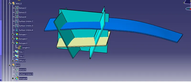
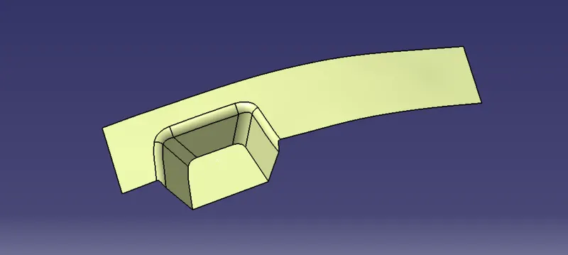
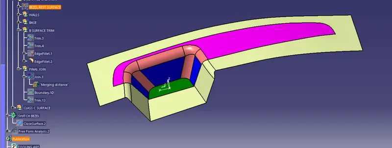
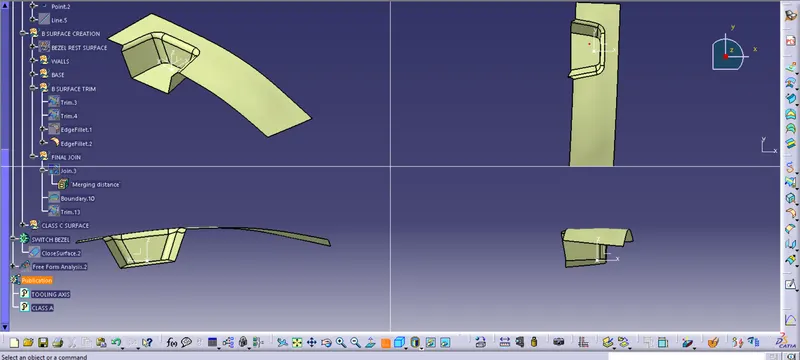
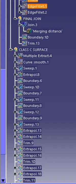
Creation of Class C- surface:-
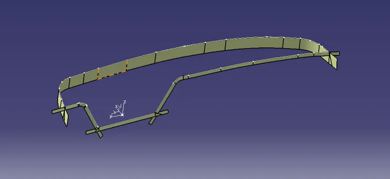
- The required outer edges of the A-Surface were extracted using Multiple Extract. Then for avoiding the patches the curve is smoothened using the Curve Smooth option.
- Then by using the sweep command the surface was created with the following feature controls,
- Profile type – Line
- Subtype – With Draft Direction
- Guide Curve – Smooth Curve
- Draft Direction – Tooling Axis
- Draft Computation Mode – Square
- Angle – 3 Degree
- Angle Sector – Positive Downward (1)
- Length – 20mm
- Trim- closed corner
- Then by using extrapolate command the edges were intersected between the surface corners which eases the trimming operation.
- Now the required portion of the C – surface were trimmed out.
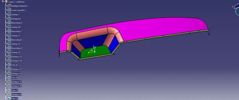
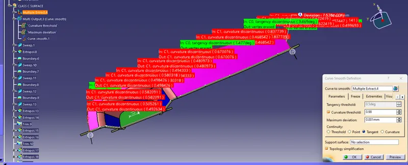
Final joinging:-
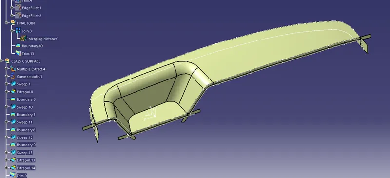
- Now the class – A and Class- C surfaces were joined together by removing the gaps in-between them with the help of extrapolation(tangent continuity) and Trim surface.
- Then the exact surface of the Switch bezel was trimmed from the above-resulted trim surface with the class-B surface.
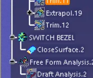
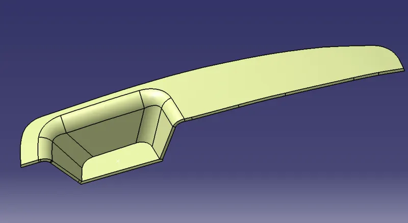
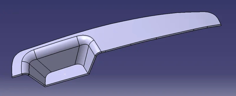
- Then, by defining the part body by using the Closed Surface command in Part Design, the component's solid body is created.
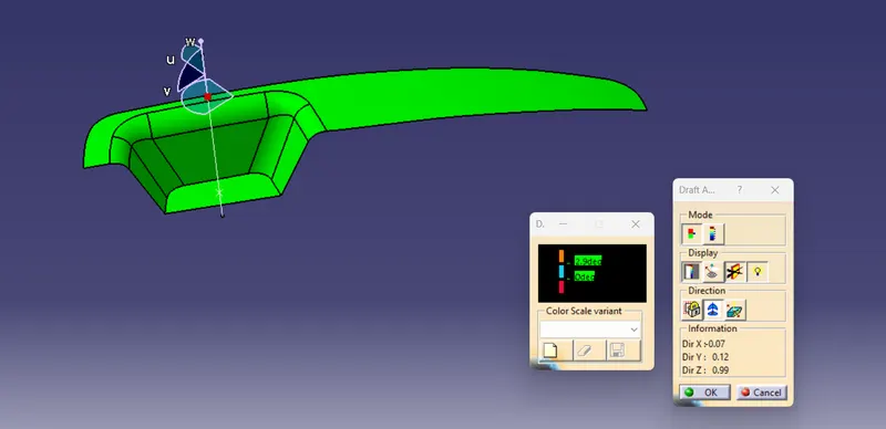
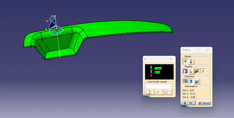
Draft analysis :-
- First we need check to Class A surface before creating the Class - B&C surface and finally the Solid body must be analysed both can done by following given below procedures.
- By changing the view mode to custom view parameters-material mode then after enabled Draft analysis
- then compass was activated and placed with tooling axis by dragging the red pointer and then lock it.
- then the quick analysis mode , the nominal value will be 3 degree and click for any where in the component and it's checked draft angle.
- then green color are shows that it satisfy the 3 degree angle .if it's not satisfy then using the Runing point tool area measured and altered get successfull draft for the created tooling direction.
Conclusion:-
Finally class A&B&C with tooling direction with publiced .Switch Bezel is moved on to the designing of the next operation – the creation of B-side features.