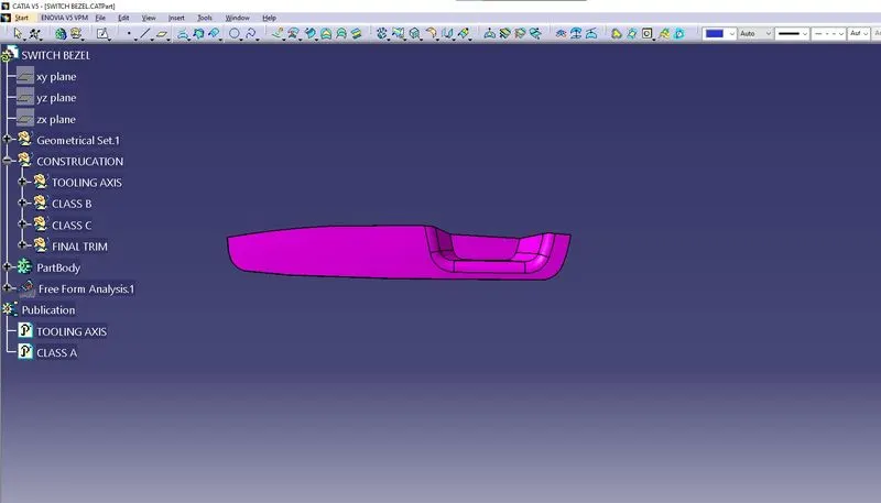
Week 8 - Challenge 2 - Switch Bezel Design
- Aim: Create the Switch Bezel Plastic component through the given Class-A surface.
- Objectives:
- To create class B & C surface for the given component.
- To form the tooling axis and capture the surface properly.
- To check the feasibility of the component with a draft of 3 degrees.
- Method:
- In order to obtain the proper draft analysis tooling axis is required and the following steps show how it is done.
- As this component has 1 hole from where the tooling axis can be generated, however it does not have proper 4 walls to generate it. In this case, an approximation is made in order to obtain the tooling axis.
- First by using the two side walls a dummy axis is made. As it is known that the draft angle is 3 degrees, the second axis is taken as a 3 degrees to the given wall and using these two axis the tooling axis is made.
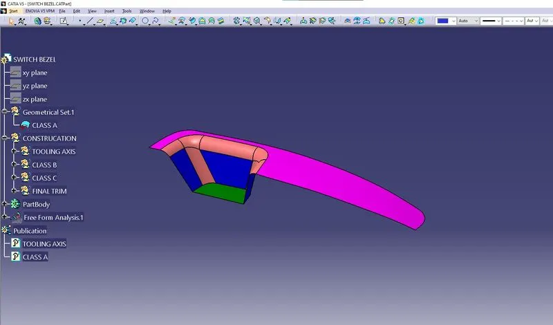
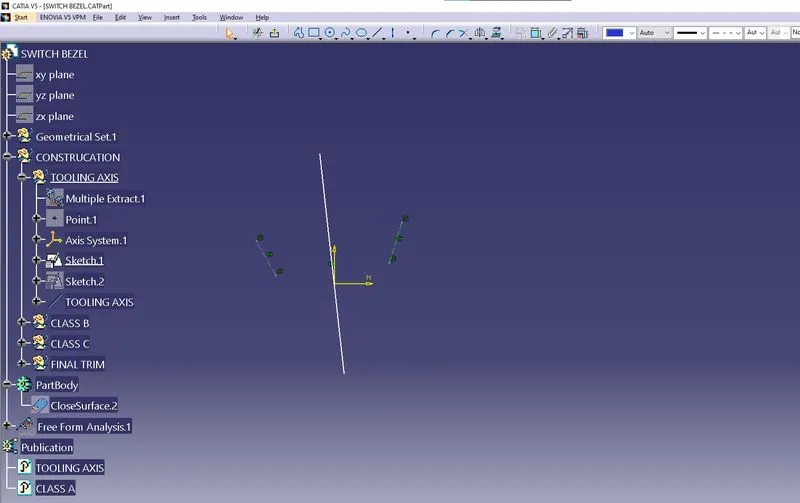
- Using the given class A surface fo the two side of the walls make the line, and use the two line to make the biesecting line
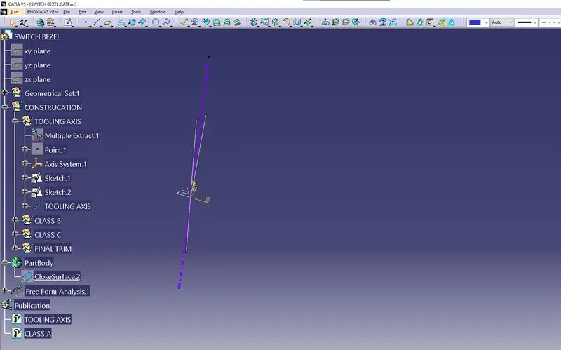
- Use the two bisecting line to form the proper tooling axis
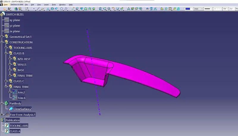
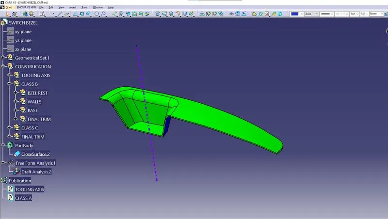
- Analysis the tooling axis is an correct direction.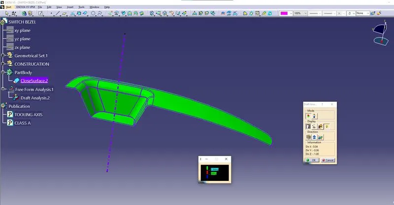
- Use the colour pattern to find the surface angle into the 3 degrees
CLASS B SURFACE:
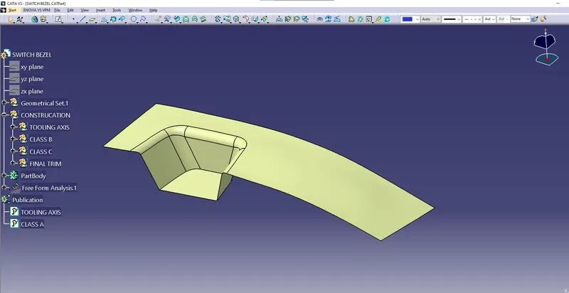
- First extract the faces of the walls, and extract bezel rest also.
- Untrim the all extract surface and extrapolated the all faces.
- Make offset the all extrapolated surface to given thickness of 2.5mm.
- After offset make trim the all surface togeather to what faces we needed.
CLASS C SURFACE :
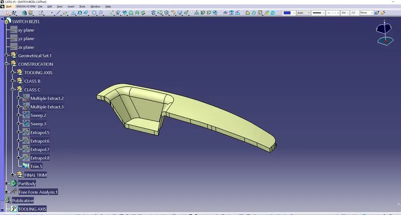
- The uses of boundry of the class A surface to make the sweep.
- To make join the class A surface and Class C surface together has single surface.
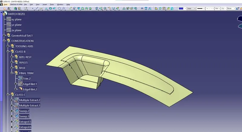
- Make the class B suface to trim to class A and C surface

- Finaly got the switch bezel part.
SOLID PART:
- ISOMETRIC VIEW :
- FRONT VIEW :
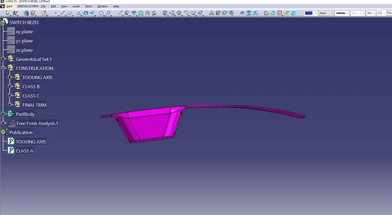
- SIDE VIEW :
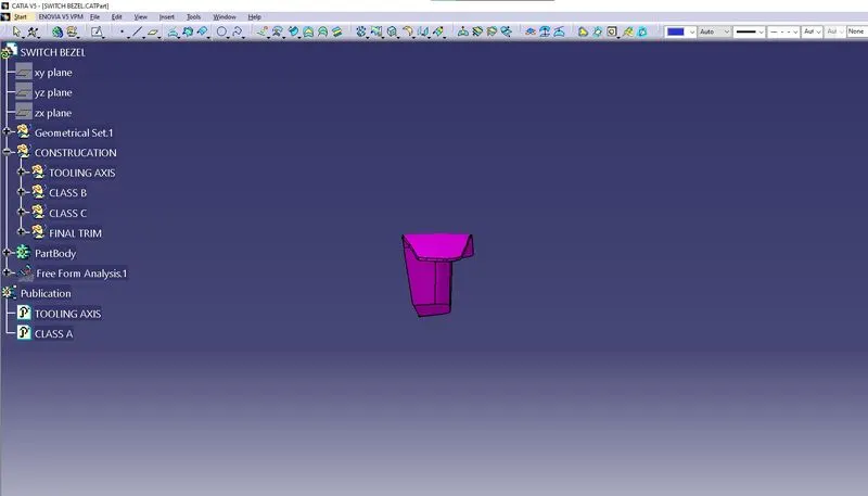
- TOP VIEW :