Week 8 - Challenge 2 - Switch Bezel Design
Draft Analysis
Class A Surface
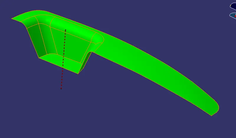
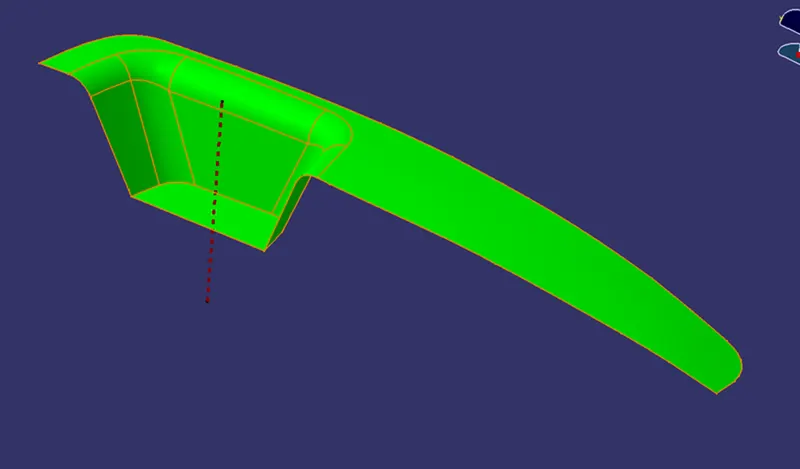
Solid Model
Solid Model Views
Front View
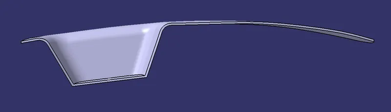
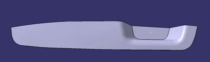
Side View
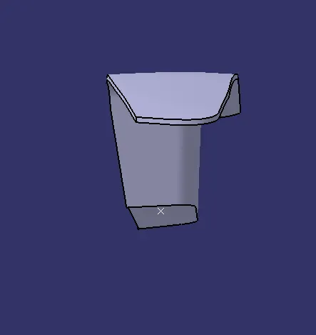
Top View
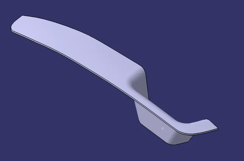
Isometric View
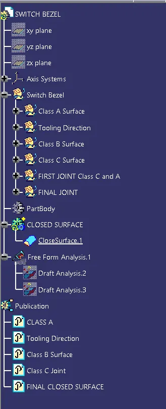
Structure Tree
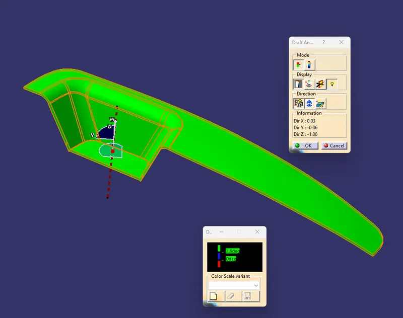
Draft Analysis
What is Draft Analysis?
This analysis done on the CAD product to see whether the model is manufacturable or not. The plastic CAD model that are prepared in CAD software are manufactured in plastic mold, so it is necessary to check whether the part is manufacturable in mold or not. Because is part in not manufacturable in mold then CAD model fails.
What is Draft Angle?
If part has a 90° of draft, then it cannot be manufactured in plastic mold, because on removal of part it may worn or tear as it creates friction on the part removal and will cause damage to the part. The recommended draft angle is prescribed as 3°, but it can be less or more depend on the accuracy needed on the model. For screw holes draft angle should not be more as it will not give perfect fit for the screw.
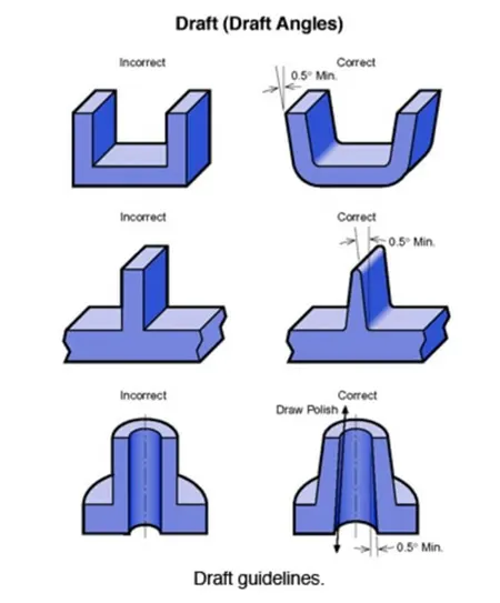
Draft using bisecting lines
In previous model we only had 2 angled walls but, in this model, we have 3 angled walls. So, here we had taken the first bisecting lines of 2 opposite wall and then we made the third line with third wall at an angle of 3° as that is minimum draft angle but we happened to vary that angel in order to get manufacturable draft angle.
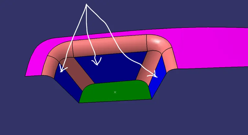
In order to create tooling direction, we have to extrude a surface and create point at the center of the surface so that we can create a tooling direction.
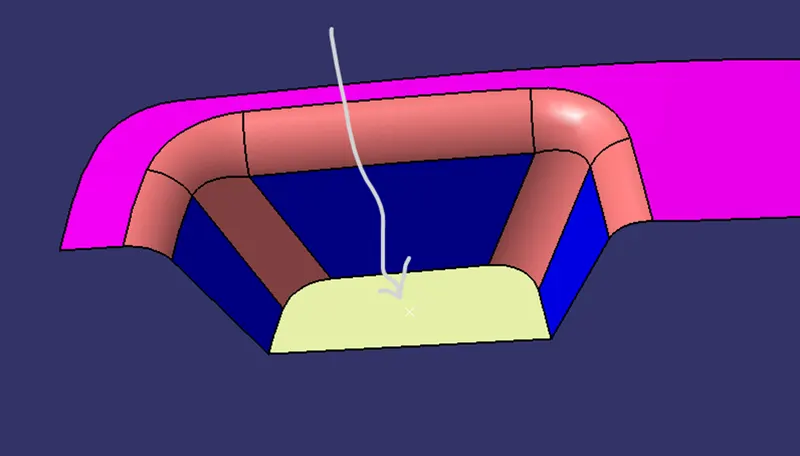
Then we create the tooling direction between 2 walls faced opposite to each other by creating axis at the center point of the surface.

- Grey color line is a bisecting line
- Red color lines are intersection lines of surface
So, we created first intersection line using two angled walls faced opposite to each other, now we have to create bisecting between current bisecting line and the third angled wall.
So, again we create a line at an angle of 3° but we happened to changed it to 5° in order to get perfect draft angle for manufacturable part.
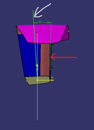
- Grey color is draft angle line for 3rd wall
- Red color line is intersection line of the model
Now, as we created the draft line for all the angled walls, we have two draft angle line one from first two walls and second from third wall. So, we create a bisecting line between these two draft angle lines to get final tooling direction.
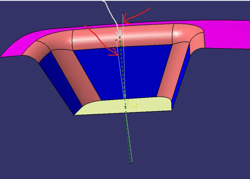
- Red color are two draft angle lines for the angled walls
- Grey color or Green line is our tooling direction
Note: - Tooling direction angle can be changed depend the kind of output we want.
So to create the tooling direction we have identify the angled walls as most of the time those are need to be delt properly but again it depend on the model and type of model.
Draft analysis: