Week 8 - Challenge 2 - Switch Bezel Design
Aim:
Create the Switch Bezel Plastic component through the given Class-A surface. To begin with, the tooling axis for the given Class-A Surface should be created meeting the requirements of the draft angle and at the end perform the Draft analysis on the model.
Take the Thickness of the component to be 2.5 mm
Objective:
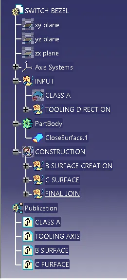
- Ensure Proper Tree Structure
- Geometrical sets should have a proper name based on the sketches present inside of it
- All the sketches should be created under the Geometrical set
- Use the Close Surface feature to make a solid body from the surface.
- Publications: Use the publication option and publish the below
- Tooling Axis
- Class A, B, and C surface
Switch bezel:
The control panel bezel is the frame part of the window switch that holds its switch covers and buttons into place. Moulding is the method used to manufacture the plastic trims of an automotive by most OEM’s, hence by considering the manufacturing consideration the switch bezel is designed.
Tooling axis-
The Tooling Direction is basically the direction that the mold pulls apart. The mold is built in two separate pieces, basically. You have a Cavity side and you have the Core side. The Core pulls apart from the Cavity and that's the Dyeline or the Tooling Direction.
BISECTING METHOD
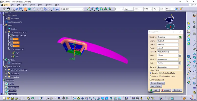
This method is used for the generation of the tooling axis for that purpose first we need to decide the direction of molding and then we create one dummy tooling axis for the reference to the purpose.
In this method, we select the surfaces which can create problems and take intersections in the x and y-direction. By using these curves we draw two lines and then draw a bisecting line from these two lines in the x-direction and y-direction.
If it is done in x-direction then it is called a tooling axis clearing x-direction and if in y then tooling axis clearing y-direction.
After completing this we need to draw a final line bisecting this two tooling axis in the X and Y directions to get our final outpu
Draft analysis-
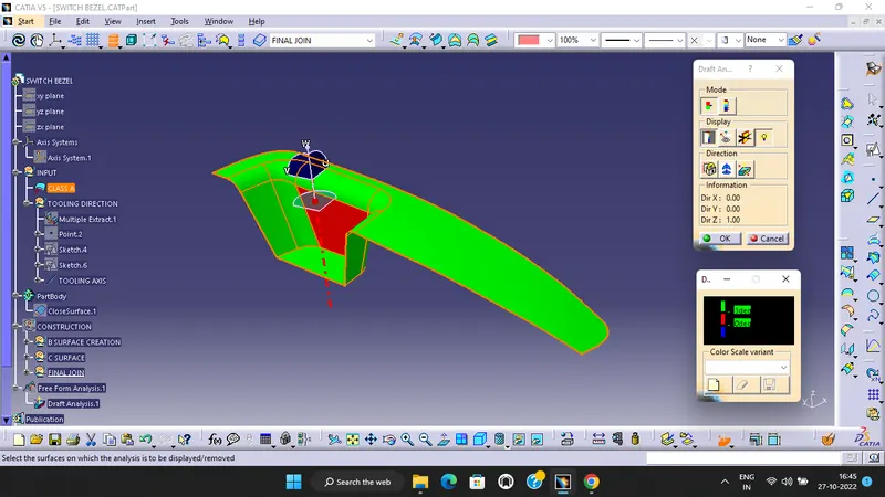
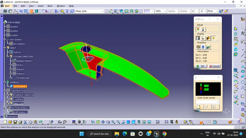
The Draft Analysis command enables you to detect if the part you drafted will be easily removed. This type of analysis is performed based on color ranges identifying zones on the analyzed element where the deviation from the draft direction at any point, corresponds to specified values.
Draft analysis class A surface:
Draft analysis final switch bezel:
Tree and publication:
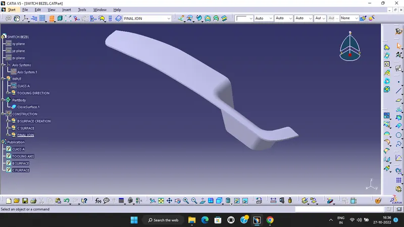
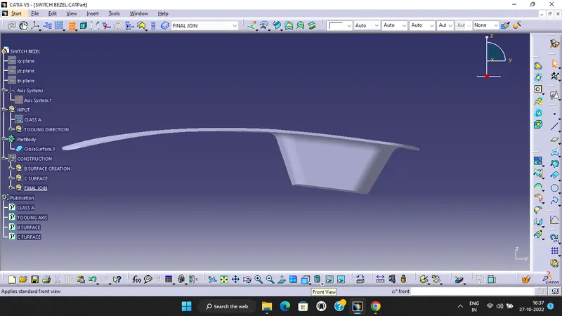
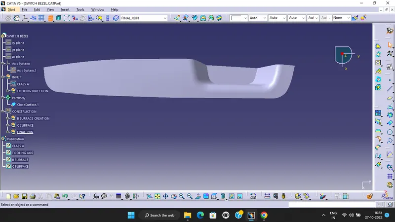
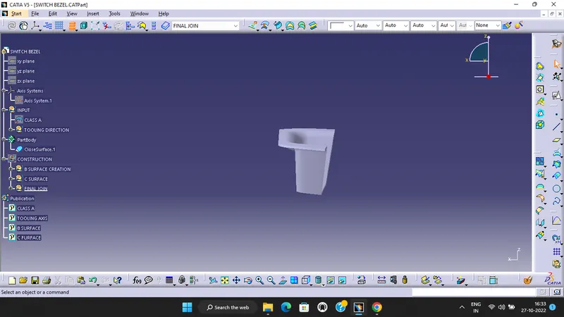
- Screenshots of the solid model with the proper color code of the draft angle in various orientations (Isometric, Front, Side, and Top View)
Isometric view
Front view
Top view
Side view
Conclusion:
The model is successfully completed as per the design requirements.