Week 8 - Challenge 2 - Switch Bezel Design
Switch Bezel Design
Aim :
To create the Switch Bezel plastic component through the given class A surface and create the required Tooling axis and perform the Draft analysis on the model.
Objective :
- First create the required correct Tooling axis and perform the Draft analysis on the given class A surface.
- Create the class-B surface and class-C surface by using the surface modeling tools.
- And make the closed surface of class-A, class-B and Class-C as the single solid body.
- And perform the Draft analysis on the solid model.
Tooling Axis :
Class-A surface is first analyzed to create the tooling axis or tooling direction that molds pull apart in injection molding. Tooling direction is important for plastic product design as it decides direction for mold separation.
Steps followed for creation of tooling axis :
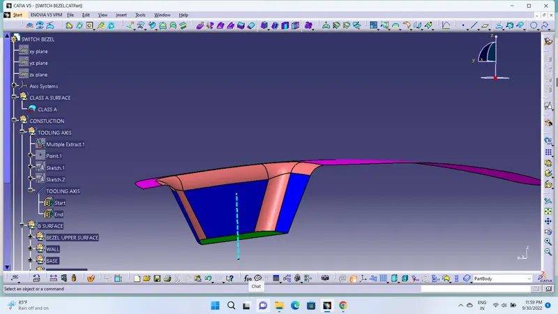
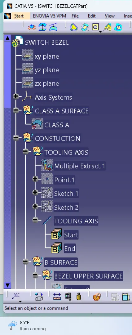
- Reference point is first created on extracted surface.
- New axis system is deployed to plot clearance lines.
- The X-direction and Y-direction along the class-A were used to create tooling axis.
- Two clearing lines were bisected to form tooling axis.
- Graphic properties of tooling axis were change before publishing.
Draft Analysis :
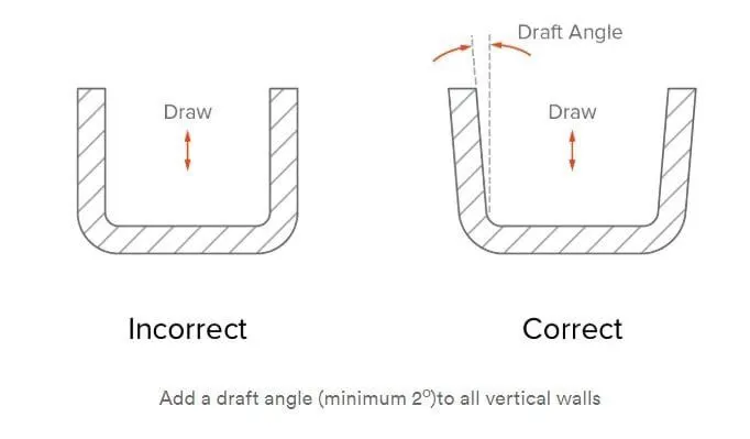
The Draft angle is the amount of taper for molded or cast parts perpendicular to the parting line. It can be measured in degrees. A functional part for injection molding has to have drafts facing both cavity and core sides to reduce the risk of damage to the parts and ensure ejection. And also important is to overcome the vaccume forces by letting air in between the metal and the plastic for the part to release properly. Adding maintaining a decent cosmetic finish.
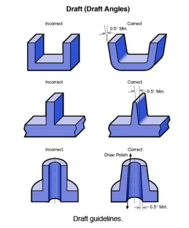
Draft should be a part of design for manufacturing and plastic product Designer should be aware of its need at the outset of the design process. This allows considerations for design requirement to be taken into account.
Nominal values for Draft angle :
- 3 Degrees is the nominal Draft angle.
- 7 Degrees for textured surface.
- At the minimum of 0.5 Degrees can be manufactured by special tools. But it will increase the manufacturing cost.
Tooling axis creation :
First step is observe the given class-A surface deeply and we can say the larger flat area which is perpendicular to the Tooling axis. So, by considering this thing for this class-A surface tooling direction is near to the Z-axis. so we create the point on the flat surface
B SURFACE:
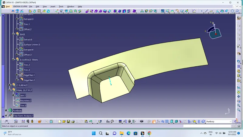
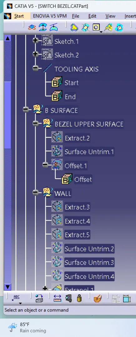
- For creating the class-B surface the required surface except the offset surface have been extracted and then untrimmed all the surface.
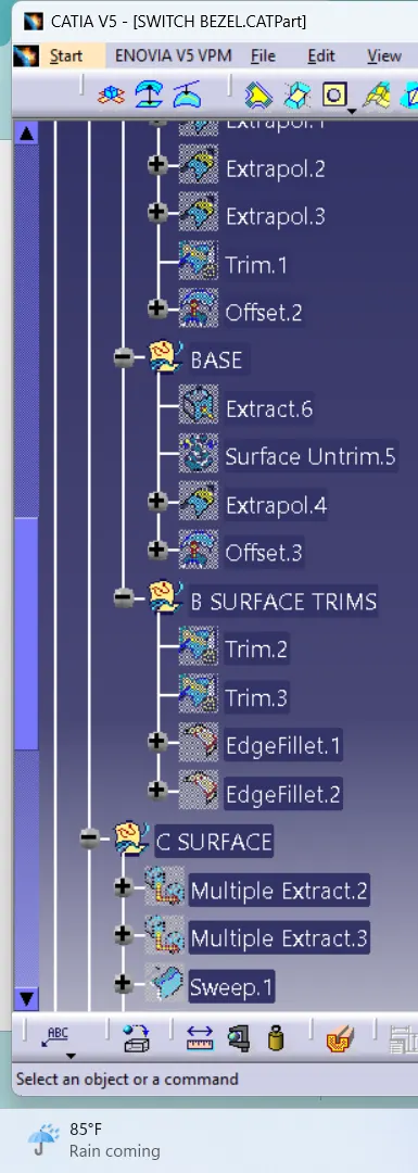
- Then all the surfaces have been extrapolated to get intersections between them.
C SURFACE:
- The required outer edges of the A-Surface were extracted using Multiple Extract. Then for avoiding the patches the curve is smoothened using the Curve Smooth option.
- Then by using the sweep command the surface was created with the following feature controls.
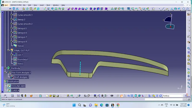
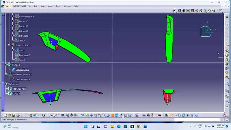
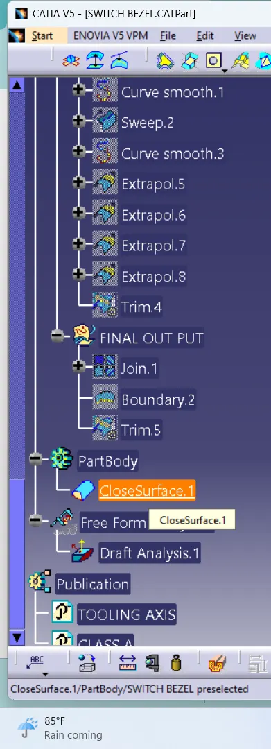
- joining of class-A, class-B,class-C surfaces th final out put as showen in figure.
CLOSE SURFACE:
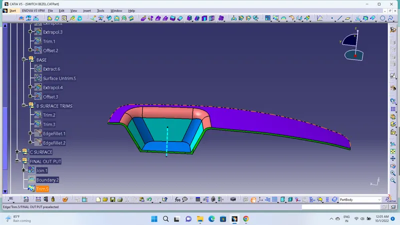
- Now the class – A and Class- C surfaces were joined together by removing the gaps in-between them with the help of extrapolation(tangent continuity) and Trim surface.
- Then the exact surface of the Switch bezel was trimmed from the above-resulted trim surface with the class-B surface.
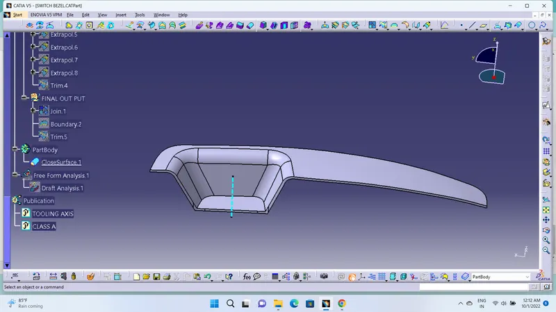
- Then, by defining the part body by using the Closed Surface command in Part Design, the component's solid body is created
DRAFT ANALYSIS:
step 1:Go to custom view parameters_ Material mode then the feature draft analysis is enabled.
step 2: activate the compass and fixed on the tooling axis and press the lock .
step3: activate the quick anlysis mode and the nominal draft angle is 3 degree and anlysis the draft angle of the compnent.
step 4: the green colure shows the satisifed draft angle of the component.
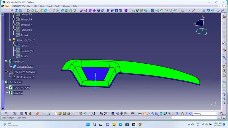
conclusion:Finally the Class – A, B&C surfaces with the Tooling Direction completed.
multi section view: