Week 8 - Challenge 2 - Switch Bezel Design
Tolling axis:-
It is the direction in which the mold opens and closes, the bevel angle that needs to be provided when considering this tool axis.
We can create the tool axis using the bisecting method.
Bisecting Method:-
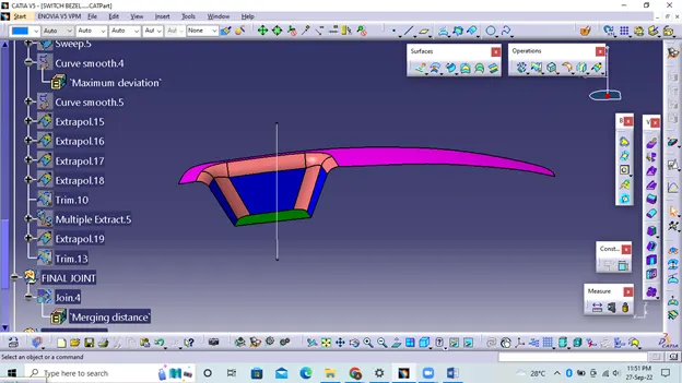
This method is used to generate the tool axis for this purpose first we need to decide the forming direction and then we create one dummy tool axis to reference the purpose.
In this method, we select surfaces that can create problems and acquire intersections in the x and y directions. Using these curves, we draw two lines and then draw a bisecting line from these two lines in the x and y directions.
If it is done in x direction then it is called tool axis cleaning in x direction and if in y direction then tool axes are cleaned in y direction.
Once this is done, we need to draw a final line bisecting these two tool axes in the X and Y directions to get the final output.
CLASS A SURFACE DRAFT ANALYSIS:-
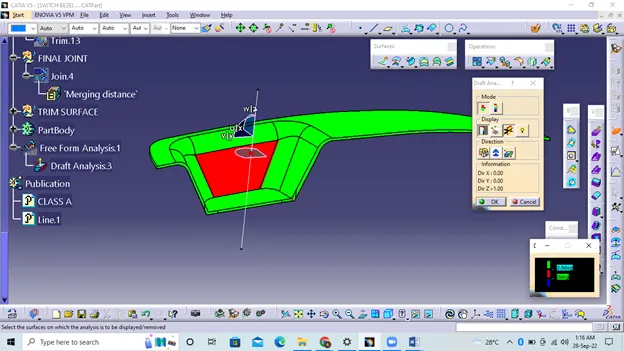
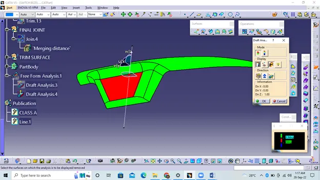
From the picture you can see that one side of the part fails the feasibility check, this happened because of the bevel angle given to the axis at the beginning. To prevent this, the angle must be increased again and an update must be performed.
CLASS B SURFACE :-
To create a Class B surface, the required surface except for the offset surface was extracted and then the entire surface was cut away.The entire surface was then extrapolated to obtain the intersections between them.Because the thickness of the switch frame is 2.5mm.
CLASS C SURFACE:-
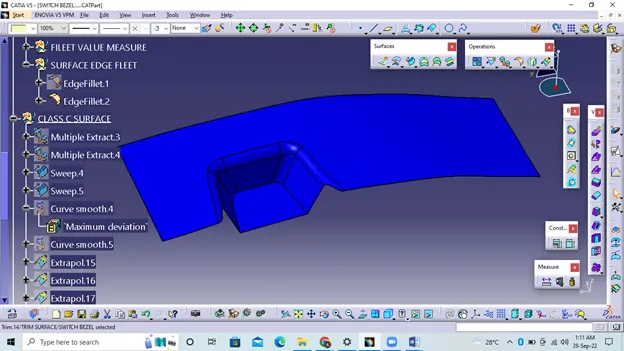
The desired outer edges of the A-surface were extracted using Multiple Extract. To avoid patches, the curve is smoothed using the smooth curve option. Then, using the Sweep command, the surface was created
After using the extrapolate command, the edges were intersected between the corners of the surface, which facilitates the clipping operation. Now the desired part of surface C has been cut.
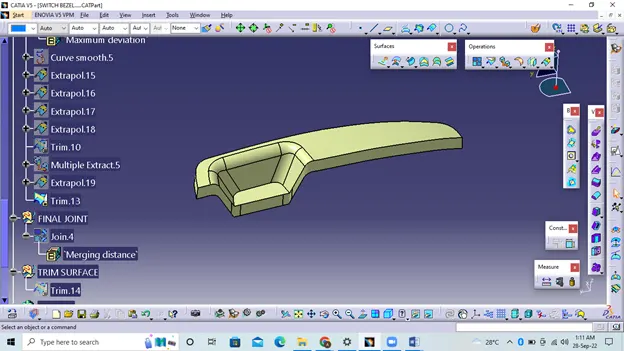
Close Surafe Creation:-
Now the Class A and Class C surfaces have been joined together by removing the gaps between them using extrapolation and Surface Trim. Then the exact surface of the switch bezel was cut from the height of the resulting trim surface with a class -B finish.Then defining the body of the part using the closed surface command in Part Design creates a solid part body.
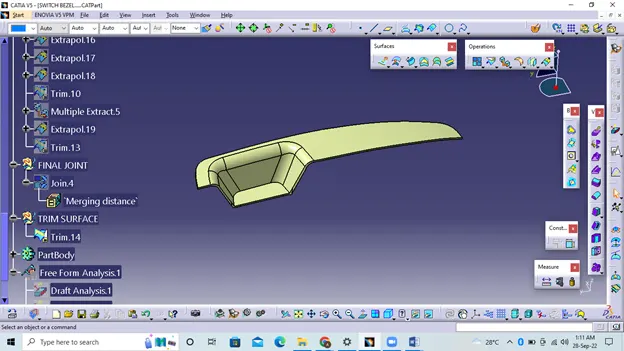
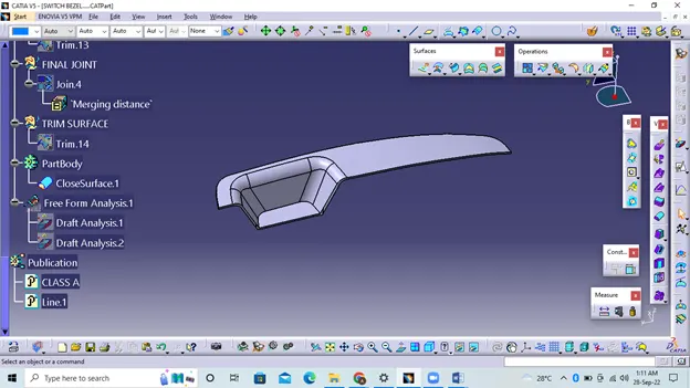
Close Surface Draft Analysis:-