Week 8 - Challenge 2 - Switch Bezel Design
Draft analysis.
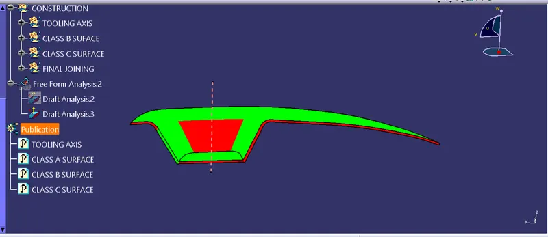
The draft analysis done on Class A surface shows that all the surface except for one lateral surface is equal to or above 3 degree of draft.
The draft analysis done on the final component shows feasible draft on most of the surface but for some surfaces it is between a zero and 3 degree angle. to eradicate this tried doing different things like reconfiguring the tooling axis, changing the sweeping direction of the class c surface etc. but the results were dissapointing
CREATING THE TOOLING AXIS
Tooling axis is an axis of movement for the core and the cavity. For the creation of tooling axis a suitable surface is chosen. A point is placed on the middle of that surface for creation of an axis system.A Point sketch is added on Axis system so as to intersecsect the surface and an intersection of the surface is made on the surface. lines which seems to create problems in the moulding are noted and an impression of it is made on the sketch and a bisecting line of the same is made. Now repeating the same procedure on the othher perpendicula plane could give you another bisecting line ( here one line for the bisector line is choosen by us because there was only one line).
Now a bisecting line of the two lines obtained is created which will be our tooling axis
pictures are given below
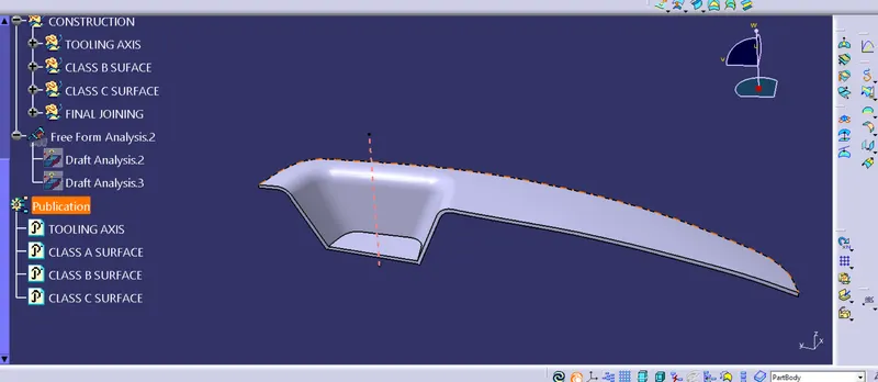
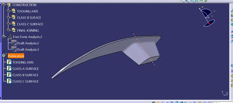
draft analysis of class a
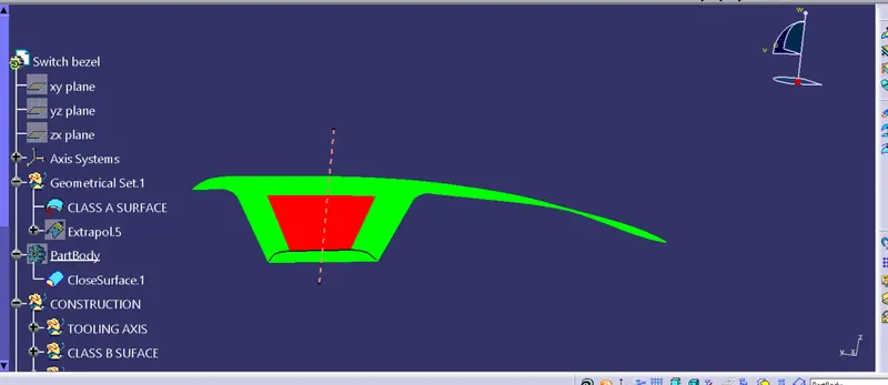
draft analysis of final product