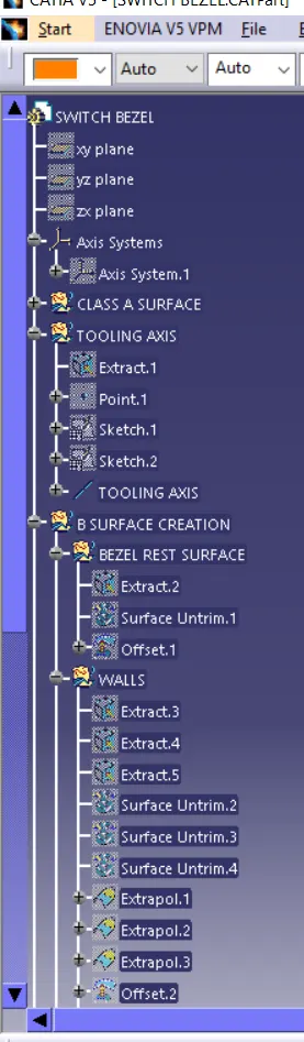
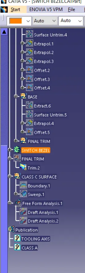
Week 8 - Challenge 2 - Switch Bezel Design
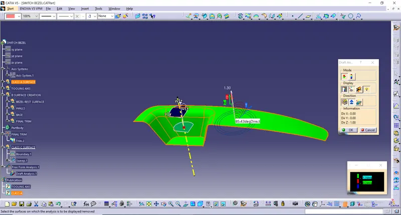
TOOLING AXIS CREATION
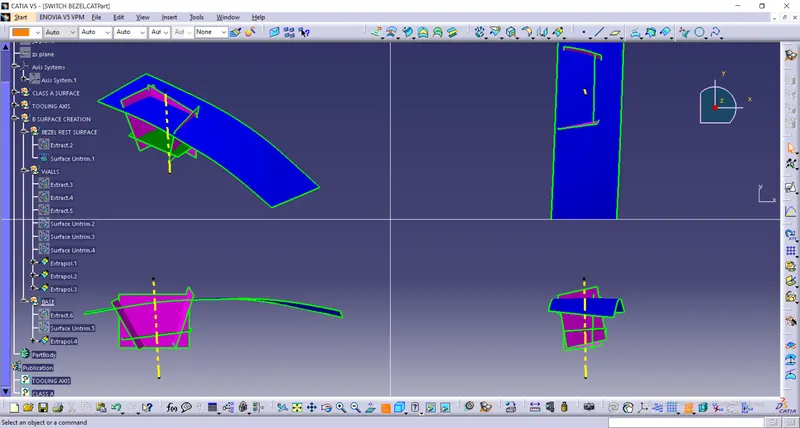
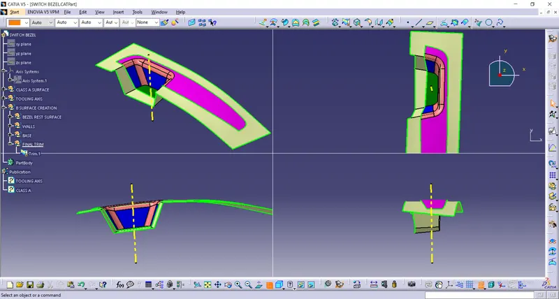
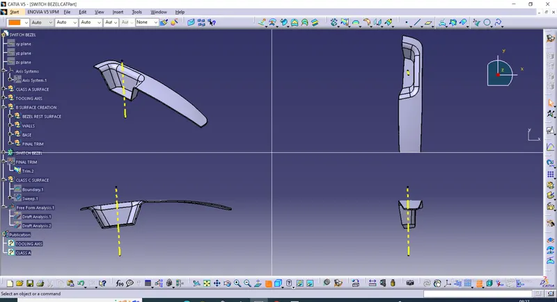
The tooling axis is nothing but the mould opens or cavity opens.Check visaully which is the best possible tooling axis.Check all three axis.Along x it possible but expensive and y is not possible z is the best possible tooling axis.Therefore the main tooling axis is along z axis
Bisecting method is used to find the proper tooling axis using the dummy tooling axis. In Bisecting method, bisecting line is used which either bisect the two line or it will show error which means the two lines are parallel to each other. In order to know whether the particular surface is toolable or not we intersect the surface with the respective plane and get a sketch which consist of two lines and with the help of bisecting line option we bisect the line which creates a line at the mid point of the two lines. Like wise we create tooling clearing axis for x and y which will be used to create the main tooling axis using the bisecting line option in in the line comand.
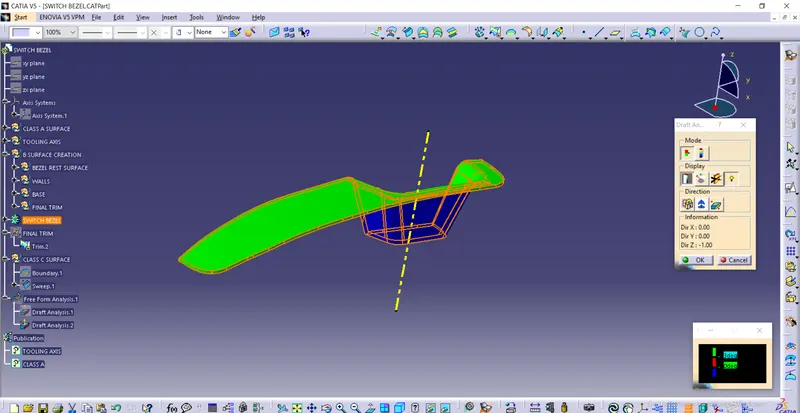
Draft Analysis
The Draft Analysis command enables you to detect if the part you drafted will be easily removed. This type of analysis is performed based on color ranges identifying zones on the analyzed element where the deviation from the draft direction at any point, corresponds to specified values.
- Click the Draft Angle icon . ...
- Check the Selection by neutral face option to determine the selection mode.
- Select the upper face as the neutral element. ...
- The default angle value is 5. ...
- Click Preview to see the draft to be created