Week 8 - Challenge 2 - Switch Bezel Design
Question:
Create the Switch Bezel Plastic component through the given Class-A surface. To begin with, the tooling axis for the given Class-A Surface should be created meeting the requirements of the draft angle and at the end perform the Draft analysis on the model.
Take the Thickness of the component to be 2.5 mm.
Solution:
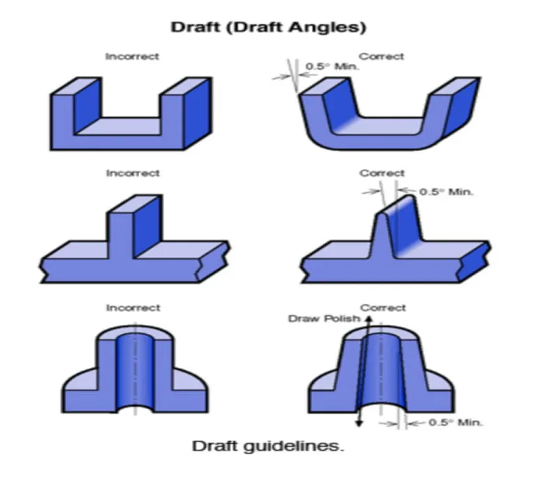
Procedure for designing Switch bezel:
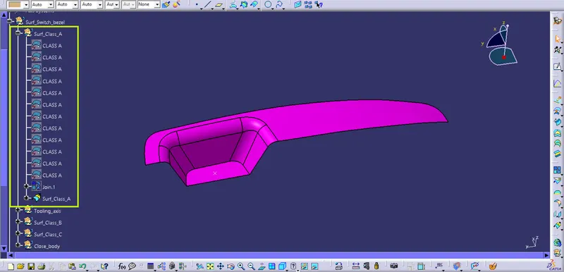
Fig1.1: Provided Class_A surface.
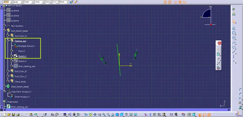
Fig1.2: Creating Sketch_01 (line_01) clearing X-direction.
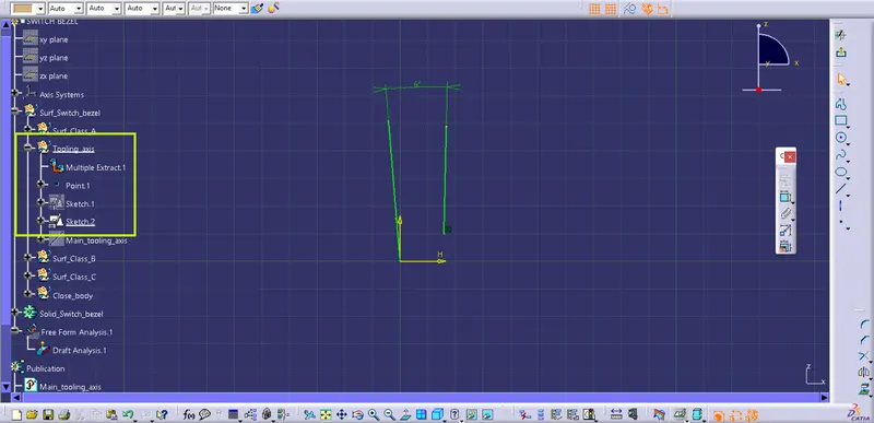
Fig1.3: Creating Sketch_02 (line_02) clearing Y-direction..
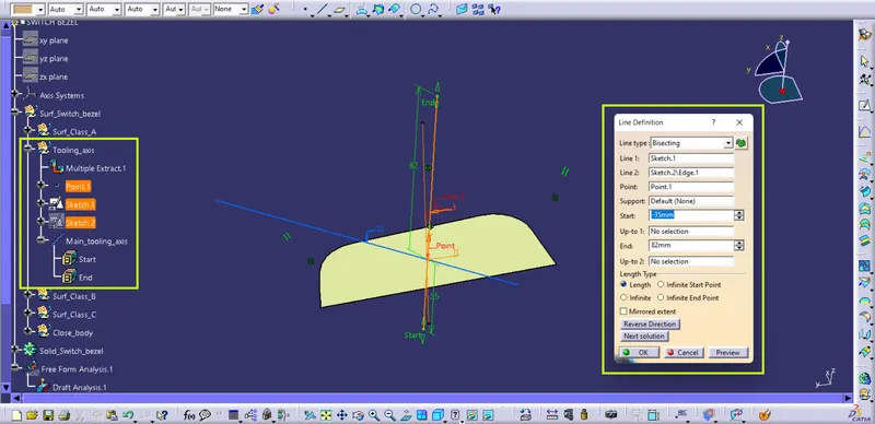
Fig1.4: Creating bisecting line at mid-point, bisecting line-01 and line-02 which is 'Main_tooling_axis'.
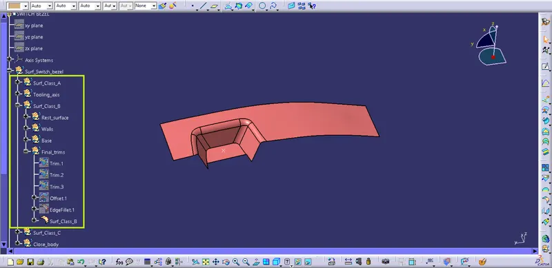
Fig1.5: Creation of Class_B surface by offseting Rest_surface,Walls and Base by 2.5 units followed by Trim and Edgefillet operations.
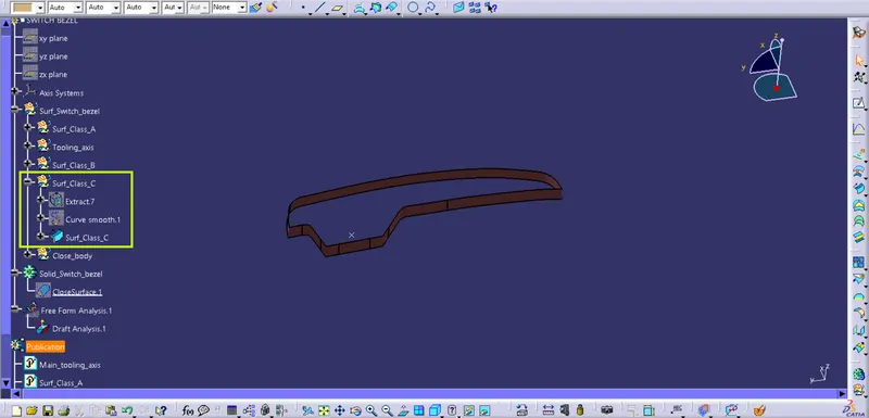
Fig1.6: Creation of Class_C surface by executing swept operation on Class_A surface's boundary as a profile.
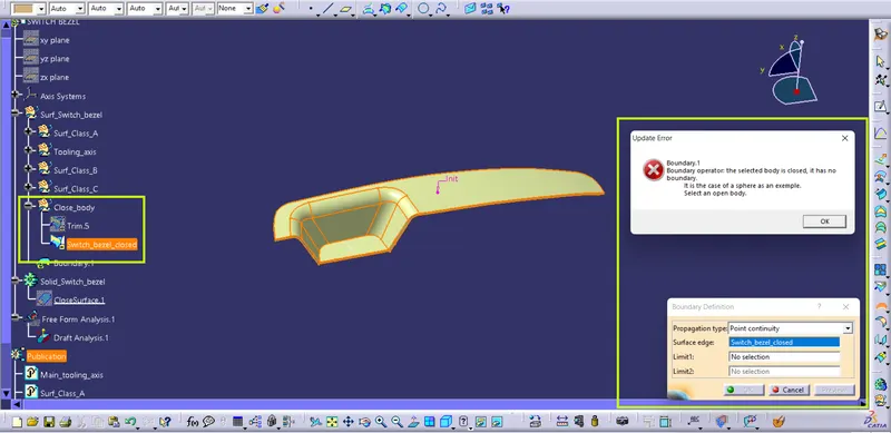
Fig1.7: Checking the closed_body of 'Switch_bezel' for boundary condition.
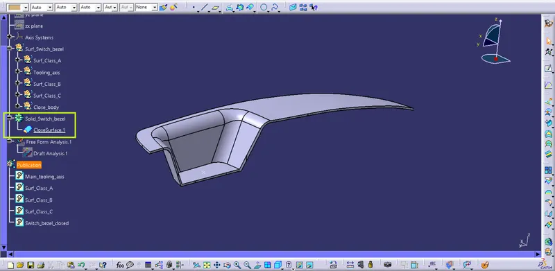
Fig1.8: Creation of 'Solid_Switch_bezel' by using the 'Closed_surface_feature' of the 'Part_workbench'.
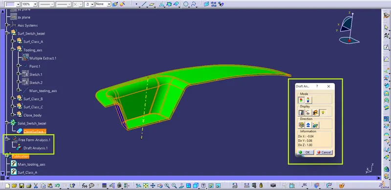
Fig1.9: Draft analysis results performed on the 'Solid_Switch_bezel'.
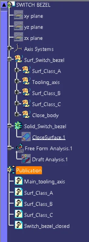
Fig1.10: Expanded tree-structure of the 'Switch_bezel'.