Week 8 - Challenge 2 - Switch Bezel Design
Switch Bezel Design
Aim
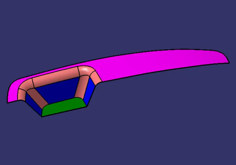
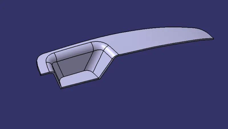
Create the Switch Bezel Plastic component through the given Class-A surface. To begin with, the tooling axis for the given Class-A Surface should be created meeting the requirements of the draft angle and at the end perform the Draft analysis on the model.
Objective
To Design a base bracket in CATIA V5 using the given Class A surface and design parameters.
Input data
We use class-A- surface as an input data
Tooling Direction
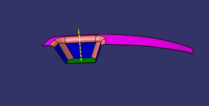
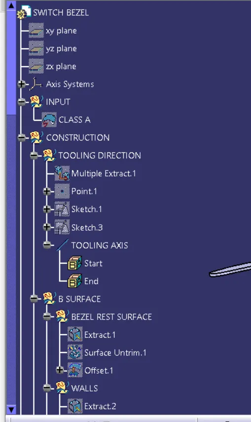
Tooling direction in which 2 halves of the mold get separated against each other. There are a lot of methods available to create a tooling direction, in this case, am going to use the bisecting method.
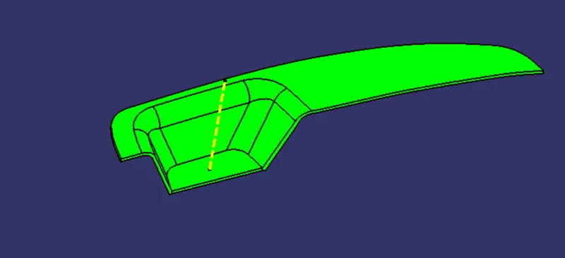
In this model am going to use bisecting method, my tooling direction in Z direction and I have a flat surface in the Z direction so am going to extract the flat face and, create a point at the center of the surface. and create a line along with the point in Z direction, Create axis system at the point and draw a new sketch on ZX plane of the axis system and create intersection curve through the surface by using ZX plane and draw a line on the intersection curve make sure the line is parallel to the dummy tooling axis and create one line at the center on the axis system and give 5 degree angle from the intersection line.
B-Surface creation
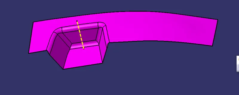
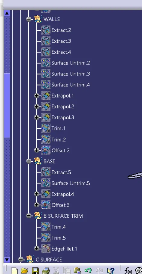
As usual B surface is created using the standard procedure by extract, un trim, extrapolate, join,Trim,split and offset commands. The B-surface is created parallel to the A-surface.
C- Surface creation
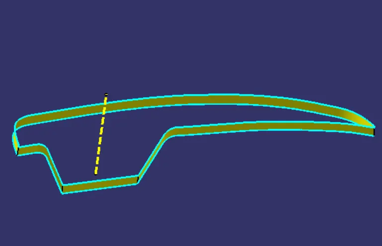
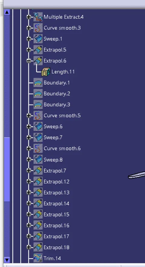
Class C surface for this component is created using the sweep command. All the ends of the component surface were facing downwards, so the C surface will create perpendicular to B surface.
To create a C-surface we need to extract the boundary of the A surface by using multiple extract command then create sweep with draft direction(Tooling direction) with 3 degree of positive draft angle .
Features Used
- Extract
- Offset
- Trim
- Untrim
- Split
- Swept
- Fillet
- Multiple extract
- Join
- Extrapolate
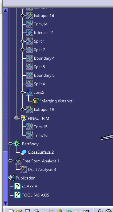
Feature Tree
Different views
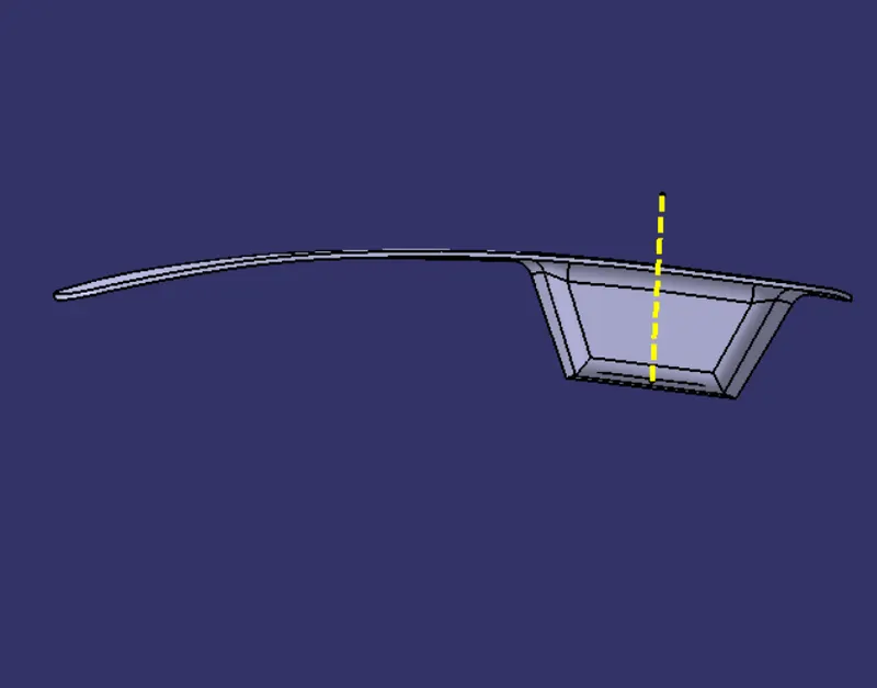
Front view
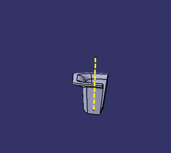
Right view
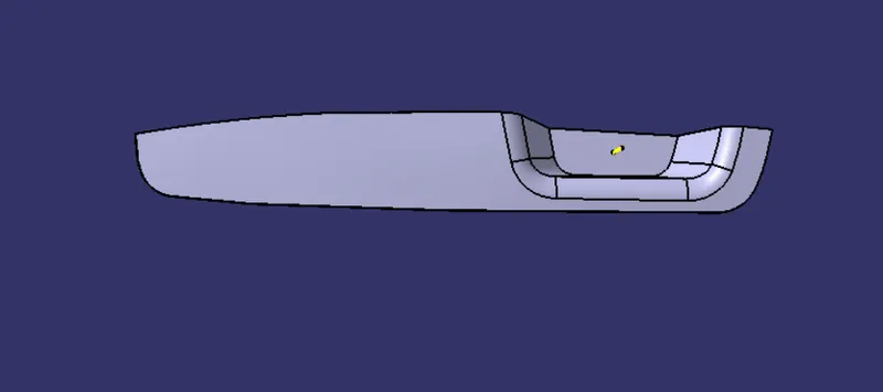
Top view
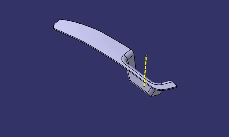
Isometric view
Converting into the solid model
Once all surfaces are created Class A, B, and C surfaces are joined together to get the final closed volume. The closed volume is then converted into a solid body using the closed volume command in the part design workbench.
Draft analysis
The Draft Analysis allows the user to easily analyze a part for a proper draft angle and check to the manufacturability of the component.
Conclusion
I have successfully completed the switch bezel challenge by using CATIA V5