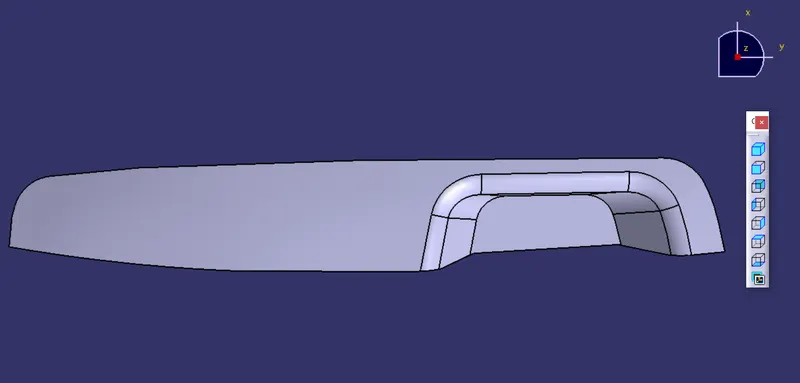
Week 8 - Challenge 2 - Switch Bezel Design
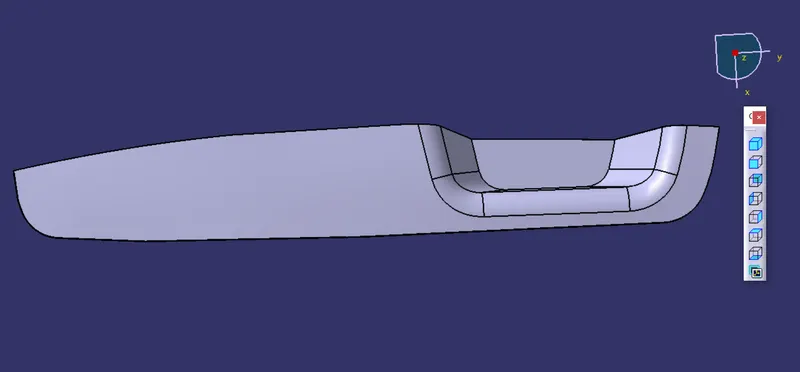
Objective: The main objective of this challenge is to create a 3D solid body from the above-given class A surface, with the help of a tooling axis of the class A surface. Perform the draft analysis for the solid part body at the end.
Tooling Axis:
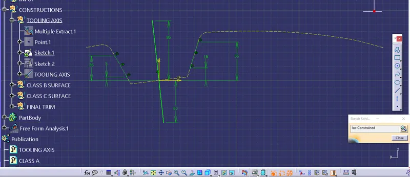
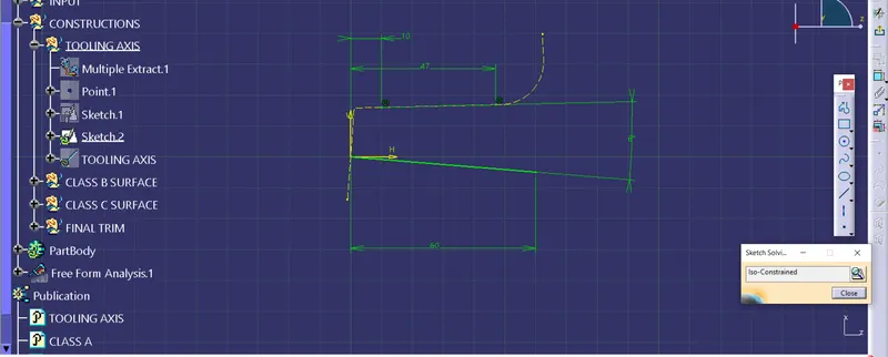
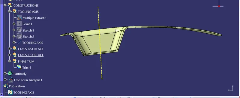
To give the tooling axis to the class A surface (the component) initially, we should keenly observe the class A surface whether the axis covers all the planes or not. I draw two lines on the intersection of the class A surface by taking the 3D reference command in the sketcher workbench after drawing a bisecting line to fix the tooling axis in the Y direction. Now we need to give the tooling axis in x-direction also, for that I selected a zx plane for the sketch. I take a cut section to take the reference in the x-direction, and I draw a line on the surface intersection and another line from the centre. The difference between the two lines is `6deg`.
CLASS B SURFACE:
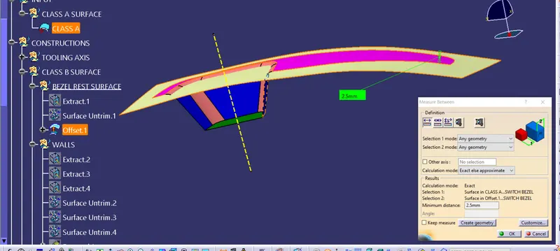
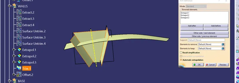
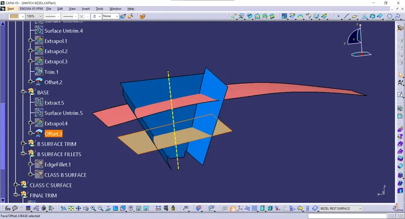
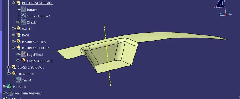
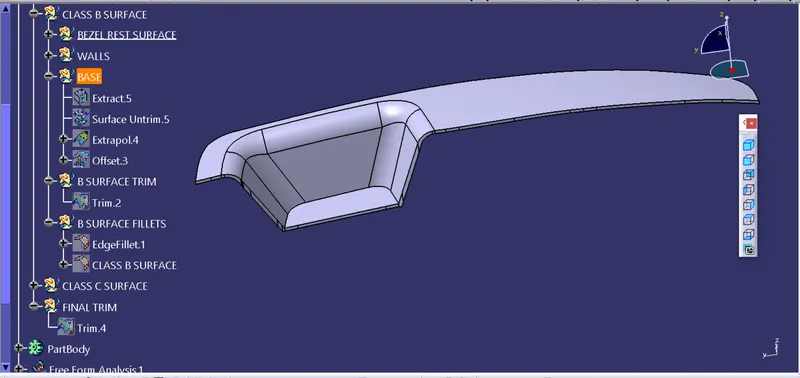
Class B is the offset of 2.5mm from the class A surface, but the fillets on the class A surface may lead to cause an error while we directly offset the class A surface. To overcome those errors I extracted the bezel rest surface, walls and base of the surface. Now, untrim those extracted surfaces and extrapolate to intersect planes with each other to get the same shape as a class-A surface by trimming those. now, I offset the trim to 2.5mm on the negative (below) side of the class A surface, after offsetting the trim give the fillets to the edges with the consideration of the thickness.
Bezel rest surface offset:
Walls:
The offset of Bezel rest surface, Walls and Base:
Final Trimmed and Filleted Class B surface:
CLASS C SURFACE:
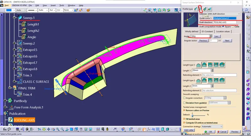
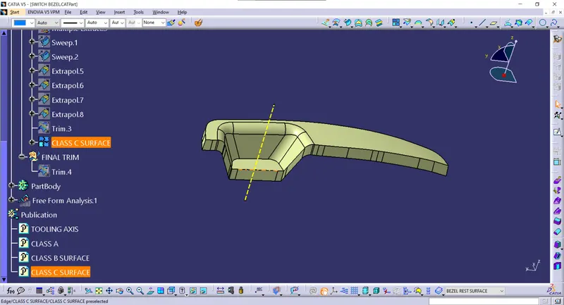
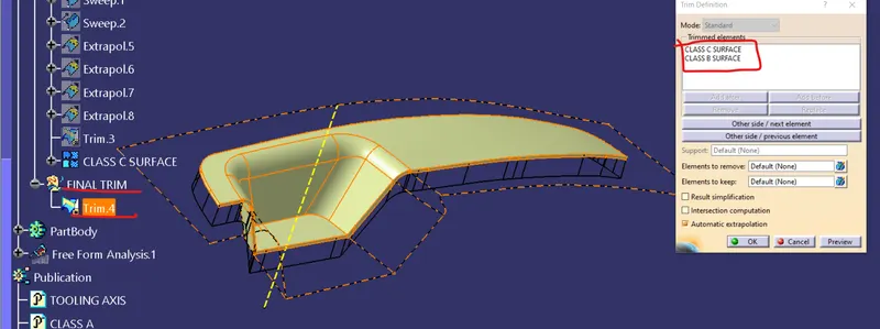
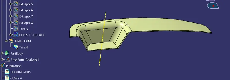
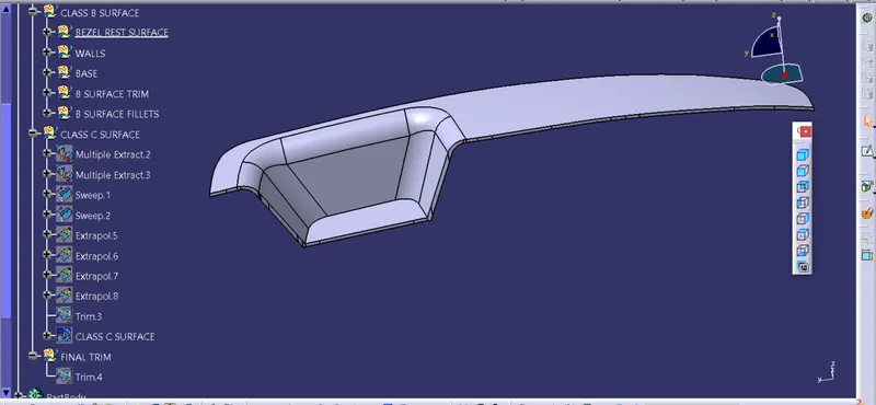
The class C surface is the combination of Class A and Class B surfaces. To create the class C surface, I extracted the boundary of the class A surface by using the multiple extract command. Now extended the class A surface boundary by using sweep command with 3 deg of draft angle. After I joined class A with an extended surface and then I trimmed that joined surface with class B surface to get a closed body.
Sweep command:
Class B surface:
Final Trim of Class A, Class B and Class C surfaces (to get closed body):
Closed body:
PART BODY:
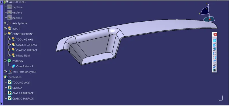
After creating a closed body, we need to create a solid body from that closed surface. Now go to the part workbench to make the sloid body with the help of the closed surface command.
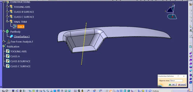
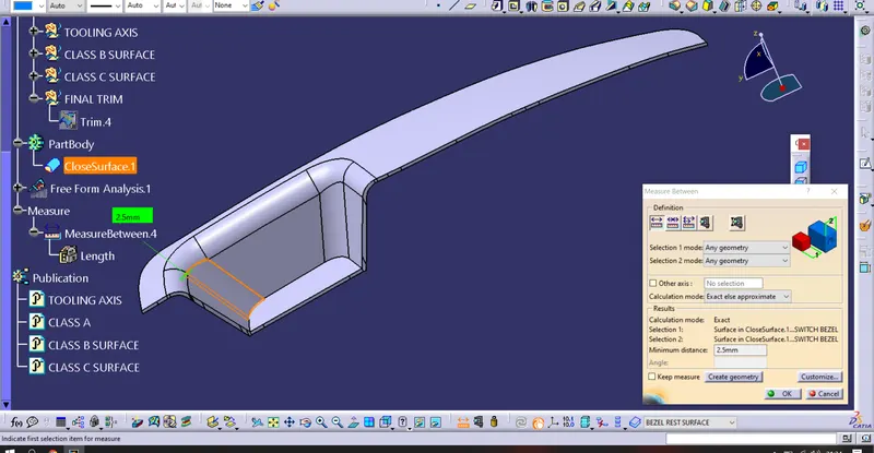
DRAFT ANALYSIS:
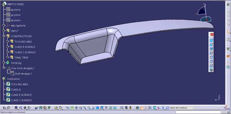
The draft analysis is done after the creation of the solid body by using the featured draft analysis command. Click on the compass symbol and align the compass to the tooling axis and give the color bar angle 2.9 deg, now check the color difference on the surface. If the surface is green color the draft angle is greater than 2.9deg (the green color limit is 2.9 deg), if the surface is red the draft angle is less than 0deg.
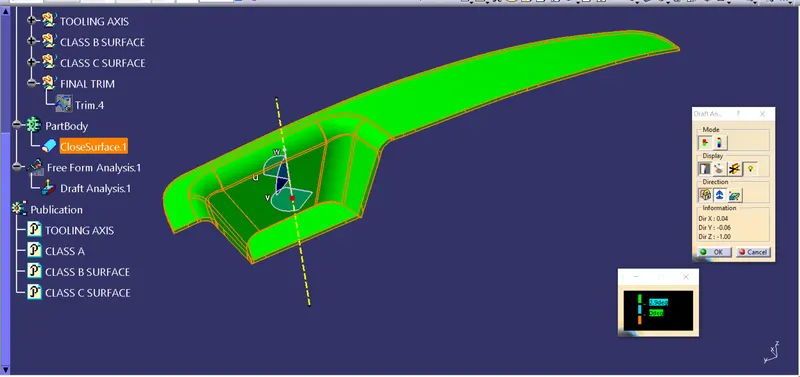
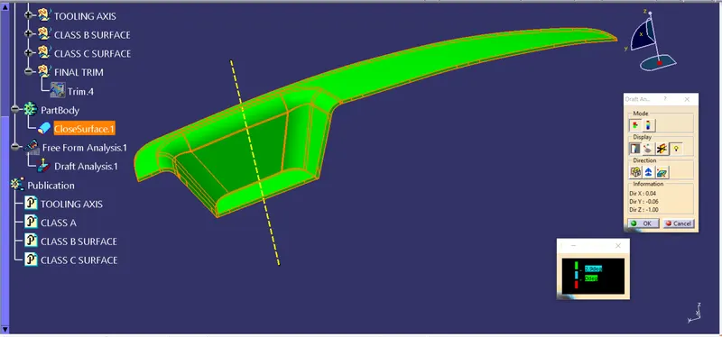
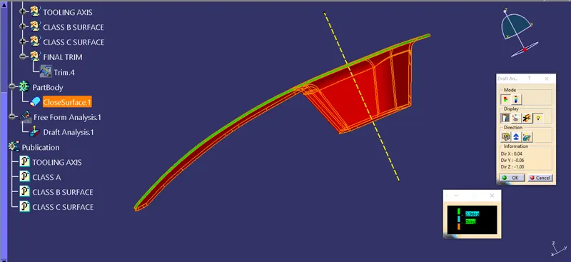
TREE STRUCTURE:
INPUT:
Class A Surface:
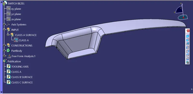
CONSTRUCTIONS:
TOOLING AXIS:
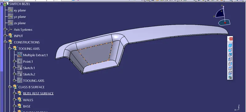
CLASS B SURFACE:
Bezel Rest surface and Walls:
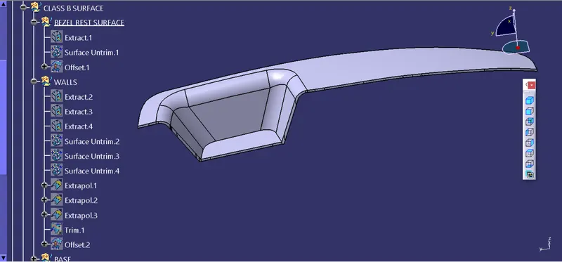
Base, Trim and Fillets:
CLASS C SURFACE AND TRIM:
PART BODY:
DRAFT ANALYSIS and PUBLICATIONS:
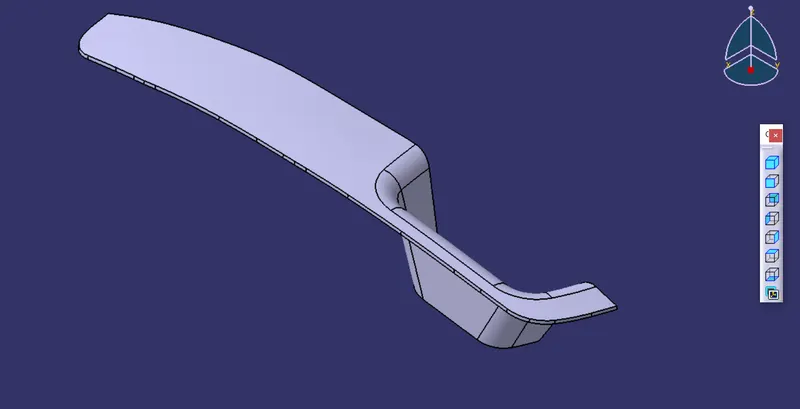
Isometric view:
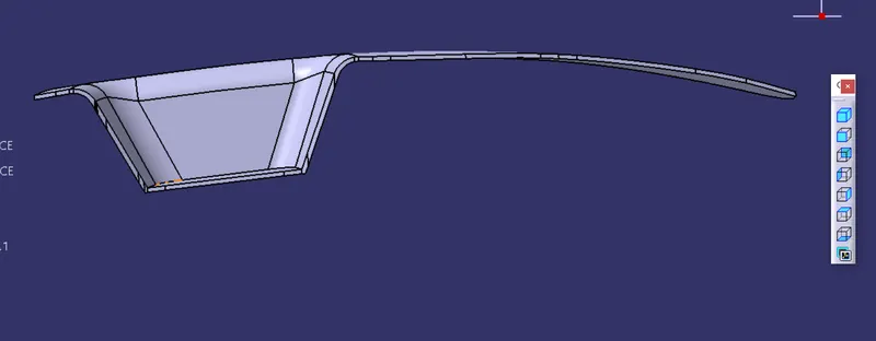
Front view:
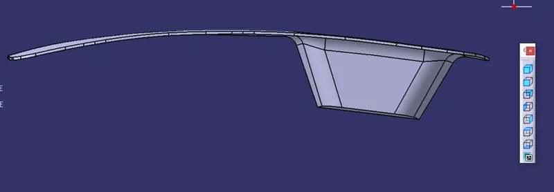
Back view:
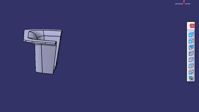
Left view:

Right view:
Top view:
Bottom view: