Week 8 - Challenge 2 - Switch Bezel Design
Arshil Kumar

updated on 22 Aug 2022

SWITCH BEZEL DESIGN- CHALLENGE 2

AIM

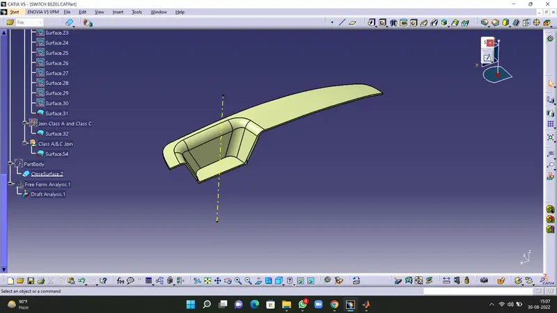
To create the Switch Bezel Plastic component using the given Class-A surface. To begin with, the tooling axis for the given Class-A Surface should be created meeting the requirements of the draft angle and at the end perform the Draft analysis on the model.


1. INTRODUCTION

A switch bezel panel is nothing but a part which consists of the switch panels for the power windows and also has some place to rest the passenger’s hand on it. It is assembled on the main door trim panels.

2. DESIGN CONSIDERATIONS

 CLASS-A Surface

 Class-A surface means visible surface. It gives the aesthetic of the component which is created by the styling team and gives to the part design engineer to create the part with all engineering aspects.

 CLASS-B Surface

 Class-B surface means thickness of a part it is not visible and is inside part. In other words, Class-B surface is a surface below a certain thickness from the class-A surface. This is the surface that contains engineering aspects of a model.

 CLASS-C Surface

 Surface that joins class-A and class-B surfaces is class-C surface. Class C is often specified for interior surfaces not readily visible, surfaces that will be covered by another part when assembled


3. THE DRAFT ANALYSIS AND THE TOOLING AXIS CREATION.

The Draft Analysis allows the user to easily analyse a part for proper draft angle. A Draft Angle describes the amount of taper for molded or cast parts perpendicular to the parting line.

Every part should clear the draft analysis test to ensure the feasibility and easy manufacturability of the component.

General guidelines for giving draft angle to a part are

0.5 degrees on all vertical faces is strongly advised.
1 to 2 degrees works very well in most situations.
3 degrees is minimum for a shutoff (metal sliding on metal).
3 degrees is required for light texture (PM-T1).
5 or more degrees is required for heavy texture (PM-T2).
Most of the parts require a minimum of 0.5 to 1 degree of drafting in order to eject from the mold without any difficulties, however 3 degree is widely accepted as the Norm.

Procedures to follow when performing the Draft analysis of the given Class-A surface are as follows


3.1 DESIGN PROCEDURE

The first thing to create the tooling axis is to analyse the class A surface through visual inspection.

To make sure that the given surface has no gap in between them. We can check it also with the help of Join or boundary commands.

Here the given surface has only one boundary which means the given surface has no patches or irregularities and it is good to go for further design procedures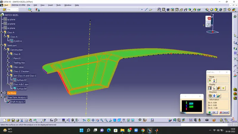
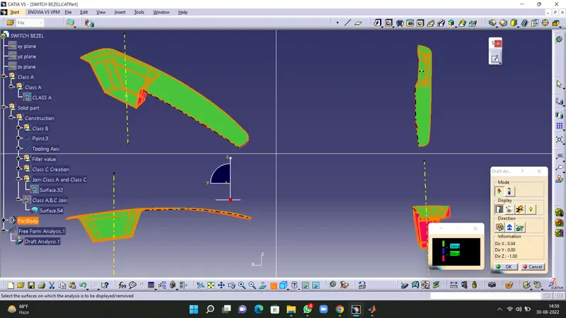
Class A Surface-
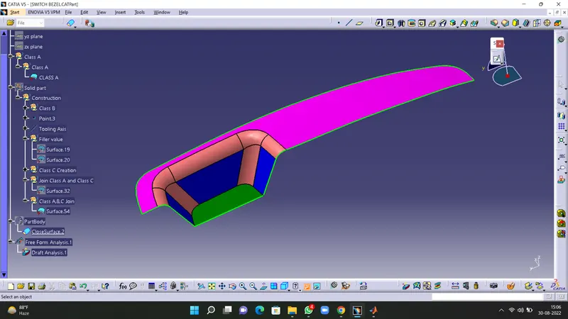
Class C Creation-
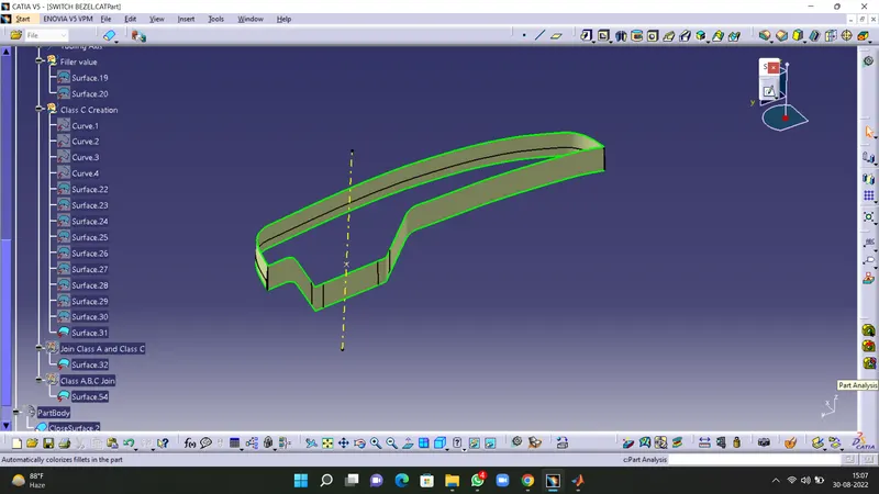
Joining A And C-
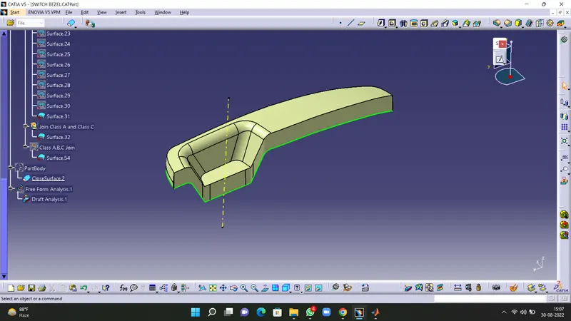
A,B And C Surfaces Joined Properly-