Week -2
AIM: 'To make a Simulick model of Doorbell using Solenoid block'.


OBJECTIVE:
* Creating a model of Doorbell in simulink and study the arm motion for the given input
  parameters.


Creation of Doorbell using Solenoid Block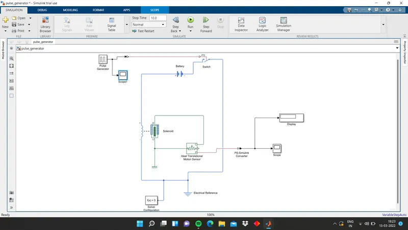
Blocks Used:
1. Battery Block: this block generate a voltage source which helps in supplying
   electrical power to solenoid block.

2. Pulse Generator: this block is used to generate a voltage pulse to the switch block.

3. Switch: Switch is used to close the circuit when rheir is an input pulse/voltage given
   to it.

4. Solenoid Block: Solenoid block is used to convert electrical energy into mechanical
   motion.

5. Ideal Translational Motion Sensor: This block is used to detect weather there is any
   linear motion in the solenoid block during the simulation.

6. Scope: Scope is used to record and plot the results of ideal translational motion
   sensor.


Connection Logic:
* step 1: Create a file name 'Doorbell' and saved it in the current directory.
* step 2: First we insert a 'Slenoid block' into our model.
* step 3: Electrical connections of 'Solenoid block' is connected to 'Battery block',
  which bypasses through the switch.
* step 4: To achive that we use a 'Pulse Generator' whch helps in creating the required
  input conditions i.e circuit should be closed '2 sec'.(using a simulink PS converter).
* Step-5: An 'Electrical reference is connected to 'negative' terminal of the electrical
  circuit.

* Step-6: An 'Ideal Translation Motion Sensor' is inserted into the model and input
  terminal is connected to the output terminal of the mechanical side of 'Solenoid
  block'.
* Step-7: Reference terminals of 'solenoid' and ' motion sensor' is
  connected to the Mechanical Translation Reference and a 'Solver Configuration' is
  connected to the same reference.
* Step-8: A 'Scope is connected to the output of 'motion sensor" by using the 'ps-
  simulink' converter.
OUTPUT:
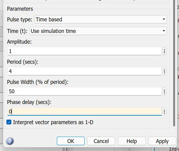
*  When the pulse generator amplitude value is 3. the movement of the plunger is low and
   high in interval 2sec.
*  Bell rings for every 2sec in a time span of 10sec.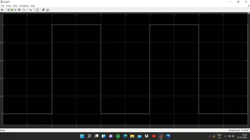
THERMISTOR:
    A thermister is a resistance thermometer or a resister whose resistance is dependent on temperature. The term is a combination of "thermal" and "resister".it is made of metallic oxides, pressed into a bead, disk, or cylindrical such as epoxy or glass.


There are two types of thermister one is NTC and the second is PTC.

NTC(negative temperature coefficient)are mostly used thermistore When temperature increase, resistance will be decreased. temperature decreases will be increased.


Input Temperatures:
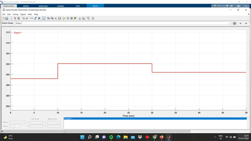
T = 20c from 0 to 10 sec
T = 27c from 10 to 30 sec
T = 23c from 30 to 50 sec

Fan Condition is:
ON if T > 25c
else OFF


SIMULINK MODEL OF FAN CONTROLLED THERMISTER :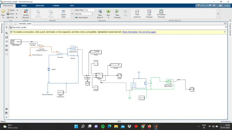
BLOCKS ARE USED:

*  Single Builder: Use the single builder to create to create and access the single
   builder block.

*  scope: Used for plotting.

*  simulink - ps converter: Converts the Simulink input signal to a physical Signal.

*  Temperature sensor: To sence the temperature. This block measures temperature in a
   thermal network. their no heat flow through the sensor.

*  Thermal referance: To grounding the thermal network.

*  Electrical referance: To grounding the electrical network.

*  Mechanical rotational referance: To ground the mechanical rotational parts.

*  Solver configuration: Defines solver settings to use for simulation.

*  Controlled voltage source: To regulate the voltage.

*  DC motore: Used as a rotating device.

*  Ideal rotational motion sensor: To sense the angular velocity and angular
   displacement of a DC motor.

*  Battery: battery is to supply voltage to the thermistor.

*  Thermistor: The block represents the NTC THERMISTOR.

*  Resistor: The relationship voltage and current and current is V=IR .
   Resister have positive and negative signs. current flowing positive to negative.

*  Controlled temperature source: The block represents an ideal energy source in the
   thermal network that can maintain the controlled temperature regardless of heat flow
   rate.

*  Temperature Source: This block represents an ideal energy source in the thermal
   network that can maintain constant absolute temperature regardless of heat flow rate.

*  Voltage sensor: this block represents a voltage sensor. it's used for measuring
   voltage.

*  Electrical referance: electrical referance port connected to the ground. A model must
   contain at least one electric port.

*  Switch: The switch block is passes through one point the second input is the control
   input.


Flow process:
*  We needto define the input required in signal builder toprovide to thermister through
   controlled temperature source. Simulink-ps converter is used to convert the signals
   to physical system.

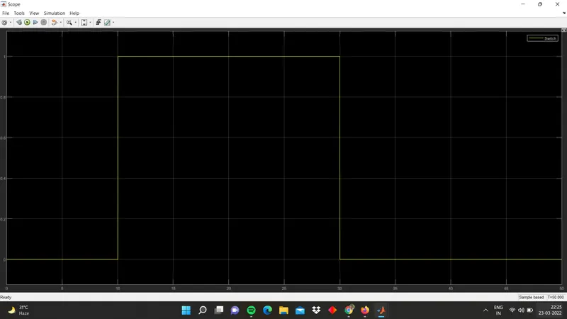
*  Through voltage sensor the threshold voltage is calculated. through this threshold
   value the switch operates to control the fan/DC motor. By using the ideal rotational
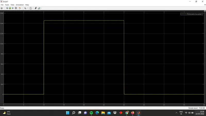
   sensor, the angular velocity and displacement values wher calculated and recorded by
   using PS-Simulink converter in display and scope.

Output:
   Input Temperature Provided:
Time vs voltage plot:
Time vs angular velocity plot:
 \
\
Conclusion:
     Hence the simulink models of Doorbell and fan- controlled Thermistor were created and observed the physical conditions.