Week 8 - Challenge 2 - Switch Bezel Design
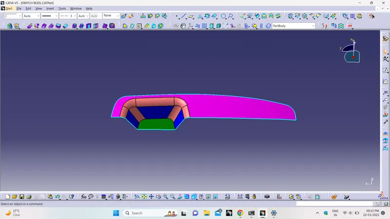
Given Class A Surface:
STEP 1
Check the connectivity of the Class A Surface
Ensure that there is no gap between the component, using join command.
We can visually check it or by clicking boundary command.
It has boundarie, only one outer boundarie.
Therefore first check completed.
STEP 2
Find the tooling axis of the component. The tooling axis is nothing but the mould opens or cavity opens.
Check visaully which is the best possible tooling axis.
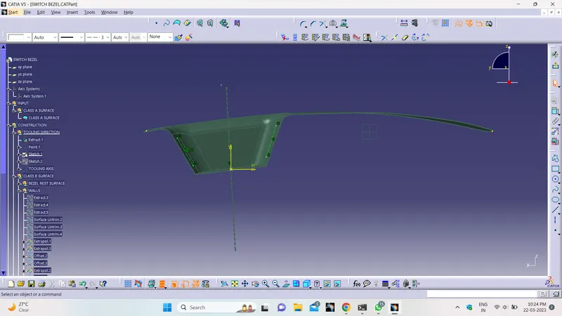
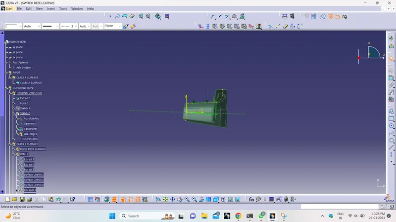
Creating a Tooling axis :
In order to obtain the proper draft analysis tooling axis is required and the following steps show how it is done.
- As this component has 1 hole from where the tooling axis can be generated, however it does not have proper 4 walls to generate it. In this case, an approximation is made in order to obtain the tooling axis.
- First by using the two side walls a dummy axis is made. As it is known that the draft angle is 3 degrees, the second axis is taken as a 5 degrees to the given wall and using these two axis the tooling axis is made.
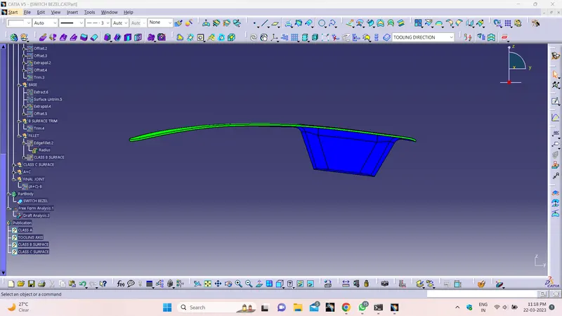
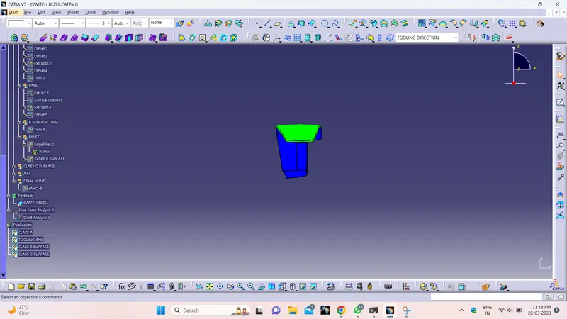
Now creating Class B Surface:
To the value of the thickness of the component to get B Surface. It is a surface it gives thickness from Class A Surface, all the
engineering features like screw bar, ribs and other supporting features could be form on the B Surface. In other tream Class B
Surface know as Engineering Surface.
To create the thickness of the class A surface along with the following steps.
Intially extracting the BEZEL REST SURFACE using extract option from Class A surface.
Then perform Extrapolate inorder to increase the length
Then Offset the surface inorder to get the required thickness
To create the bezel rest surface area.
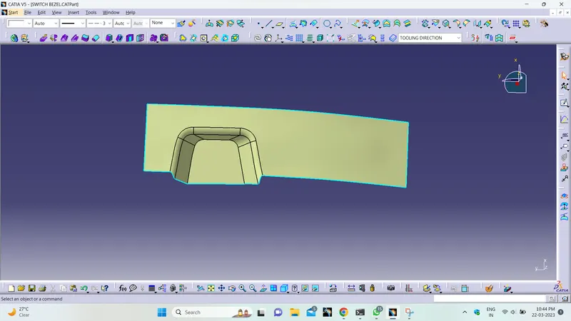
Now similary create the walls and base of the switch bezel.
Then triming all unwanted extra surface.
Then give the correct fillet values to avoide sharp edges.
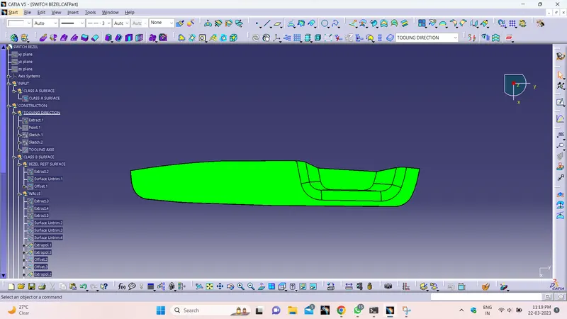
Below figure is know as Class B surface.
Now creating Class C Surface:
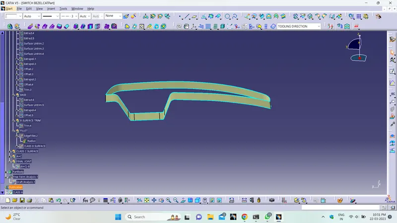
The purpose of Class C surface is to connect Class A surfaces & Class B surfaces.
It gives thickness of the model.
Surface operation:
To help of sweep command it create some thickness of profile
To trim the unwanted surface of class C surface.
The below figure is know as Class C surface.
CLOSE SURFACE:
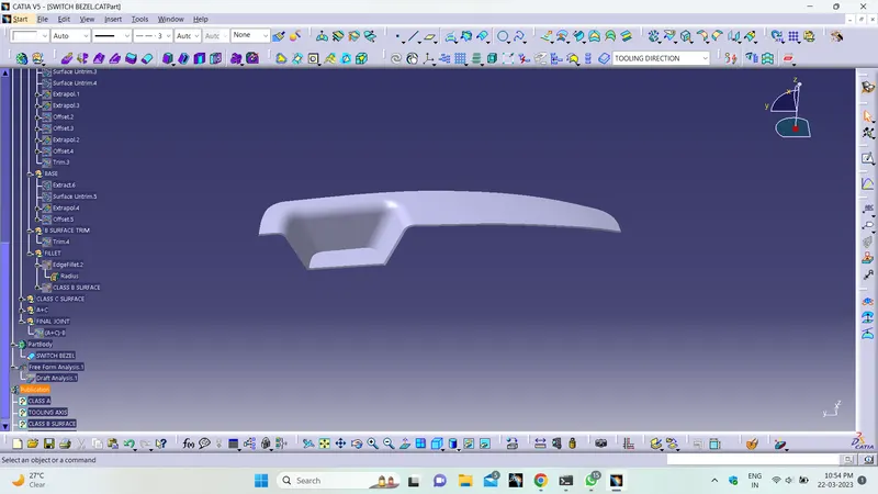
Close surface is alos known as thickness of the model.
Go to part modeling & click the close surface option it create complete model of surface.
Give the thickness of switch bezel is 2.5mm.
DRAFT ANALYSIS:
Change view mode
Customize view parameters.
Choose the material in shading option.
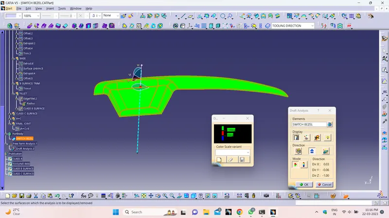
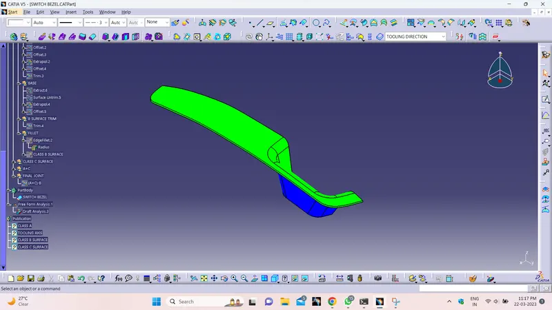
Use draft analysis option for class A surface and Tooling Axis.
Go to INSERT – ANALYSIS – FEATURE DRAFT ANALYSIS.
CONCLUSION:
At the end of this model, we can get the complete profile of base bracket, also the thickness of the component.