Week 10 - Challenge 3 - Door Trim Lower with Engineering Features
AIM: Create the Door Trim Lower Plastic component through the given Class-A surface. To begin with, the tooling axis for the given Class-A Surface should be created meeting the requirements of the draft angle and at the end perform the Draft analysis on the model.
Create the Heat Stakes and the locators considering the design rules mentioned in the video for the door applique.
PROCEDURE:
1. Open the given class A surface. Ensure that all its boundaries are connected.
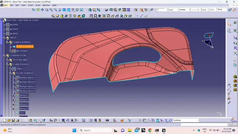
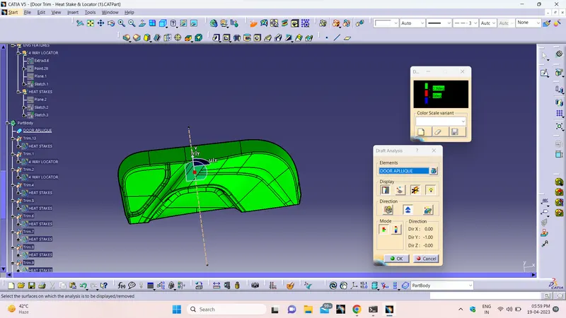
2. Tooling axis: To create the tooling axis first we have to check the best suitable direction for tooling by using the compass. the y direction is suitable for creating the tolling axis because in the y direction most of the surfaces are clearing while performing draft analysis. Generally tooling axis is created using bisecting line method but here A line normal to the surface is created in the y direction and considered the tooling axis.
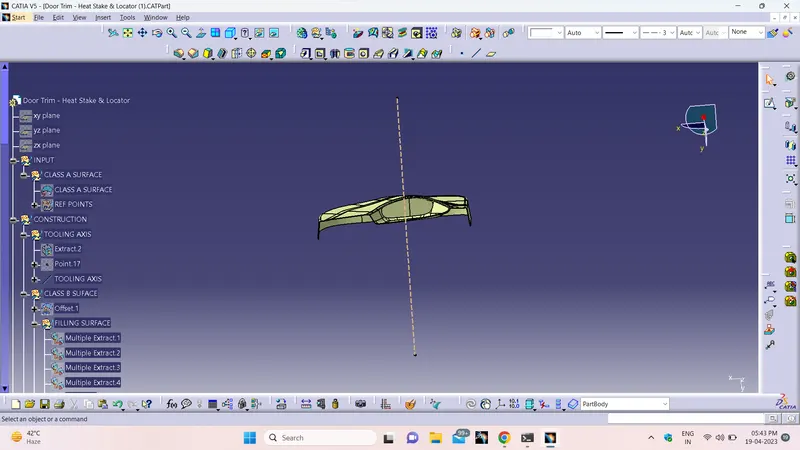
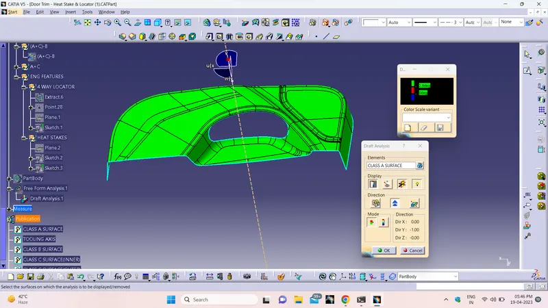
3. performed a draft analysis check from that line whether the created tooling axis is in the correct position or not. If in the draft, analysis check the surface highlighted with green colour on both sides of the surface the tooling axis is in the correct position and direction.
4. Create a B surface at an offset of 2.5mm with respect to the A surface given. We can notice that few of the elements will be missing after offset. Using features like the extract, extrapolate, multisection etc, fill up the missing elements.
The B surface will look as below after following the above procedure.
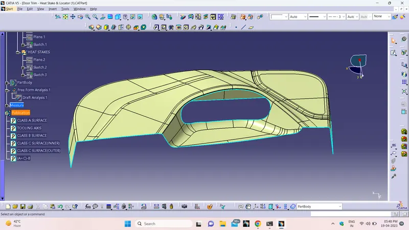
5. Using Sweep option Create the C surface as shown below.
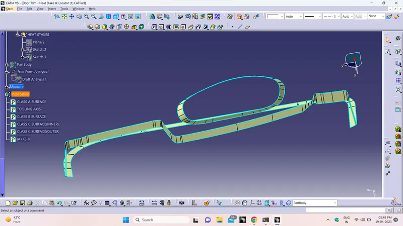
6. Join the C surface with the A surface.
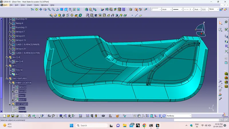
7. Trim the B surface with the above surface to obtain a closed hollow body using surfaces.
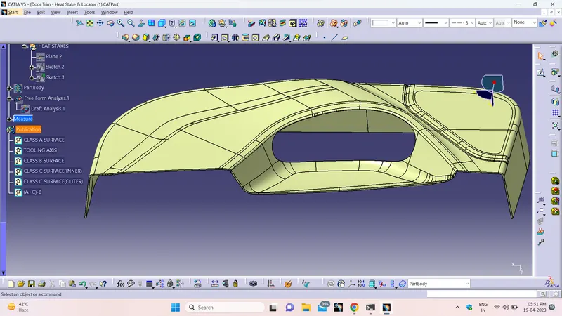
8. Convert the surface body into part body using the feature close surface.
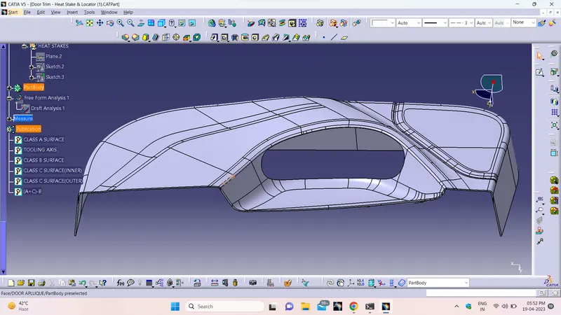
9. Perform Draft analaysis on the solid part.
Below this image help me to create Engineering Features on B side
10. Create a 4 way locator using a sketch on the body. After creating the sketch, pad it 25mm in height and thicken it to 1.3mm and draft it with 0.5deg in the direction of the tooling axis. Give 3mm of chamfer with 45deg of inclination and a fillet of 0.3mm and 3mm radius
Use copy and paste the 2 nd 4 way locator using the translate feature.
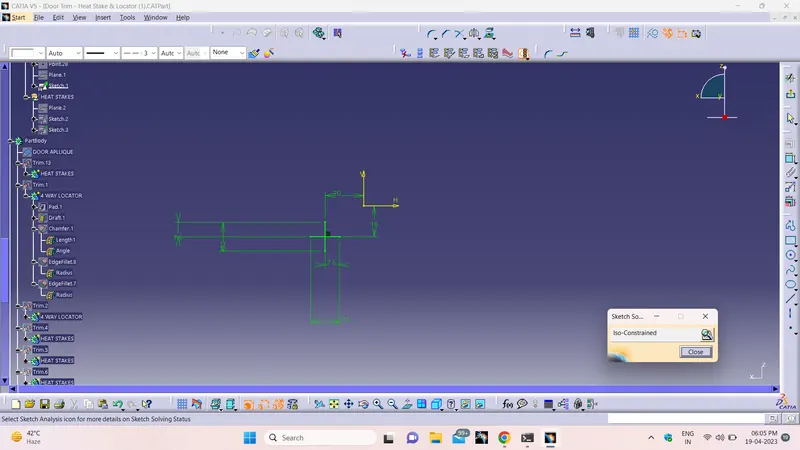
11. Create Heat stake. Draw a sketch on the surface. After the creation of the sketch, Pad it to 20mm height and a draft angle of 0.5deg on both sides (inside and outside). After creating the heat stake, create the ribs for supporting purposes. To create the ribs, draw a sketch and padded it to height less than that of the heat stake and 1.2mm in thickness. After padding the ribs, drafted 0.5deg in the tooling axis direction and fillet it with a 0.25mm radius. Finally, use union trim on the ribs with a heat stake to remove the ribs as per the requirement, which are present inside the heat stakes.
Copy and translate the heat stake to all the positions as needed
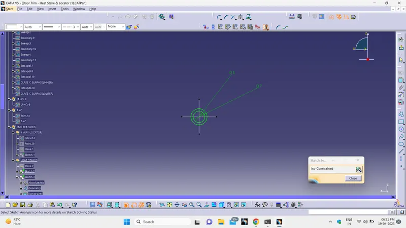
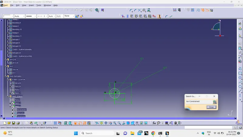
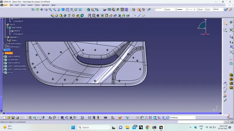
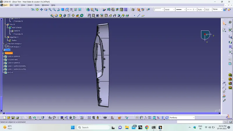
12. Create Engineering Features as shown below.
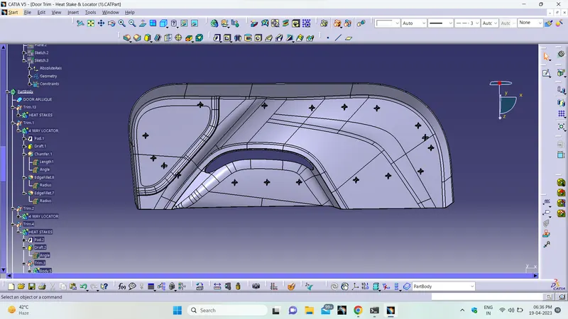
13. Perform draft analysis on the part. for inspecting the features which are added later on the B surface.
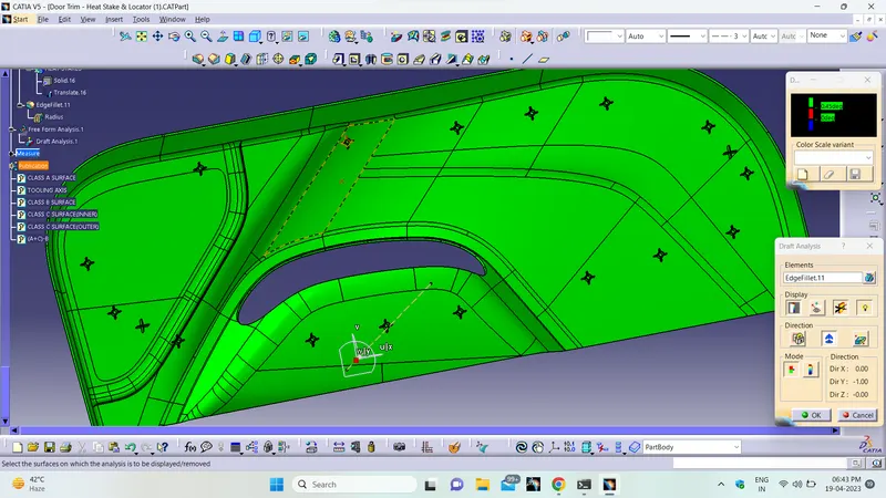
From above we can find that the componen is manufacturable.
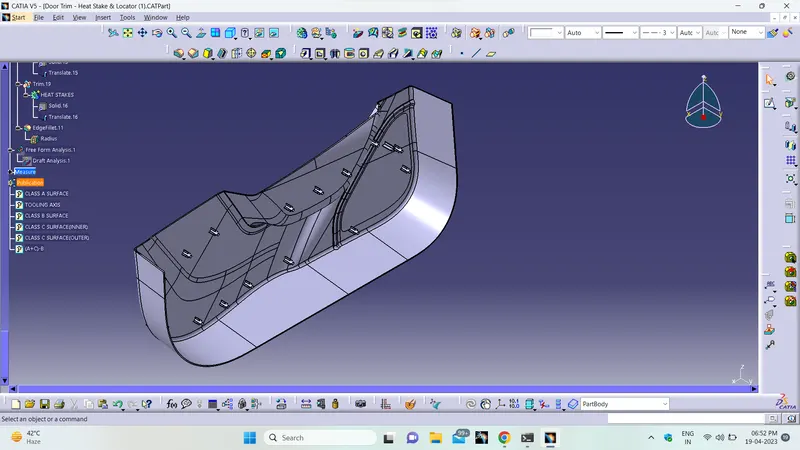
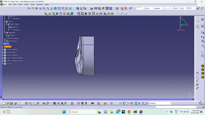
Views:
CONCLUSION:
Thus by following the above we crate the door trim with B class features (heat stake and locator pins)