Week 8 - Challenge 2 - Base Bracket Design
Base Bracket Plastic component
Class A-surface:
Class A surface was given as model and have to work on the model.
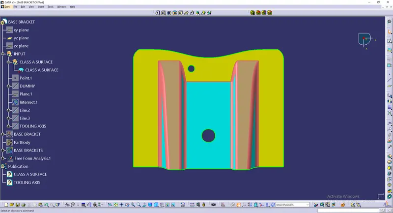
Class B surface
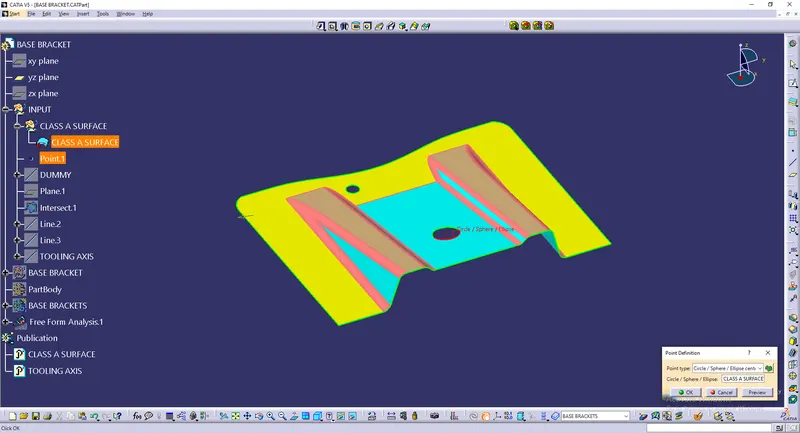
A point is created in the center of the circle from the class A surface.
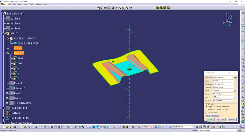
A line drawn from the point created and extended in the direction of Z component. This line is known as Dummy axis.
A plane is created as Parallel through point from the point created by taking the yz plane as reference.
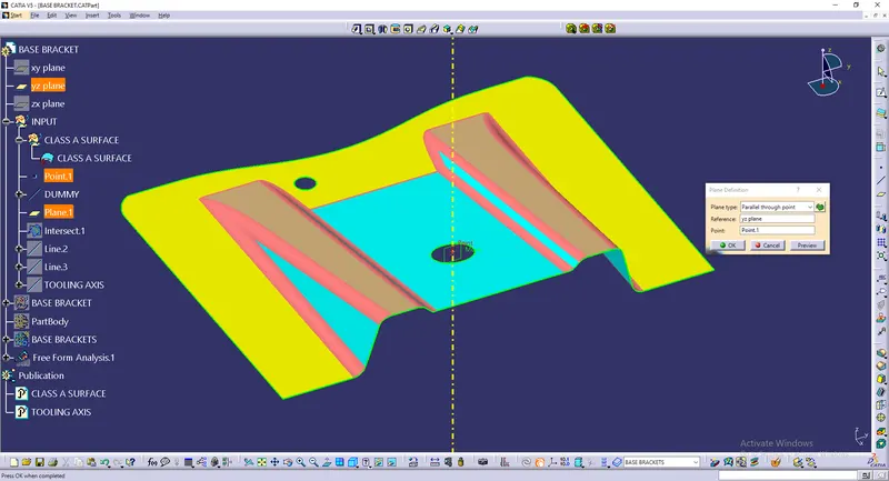
The Class A surface is taken intersection with the plane created.
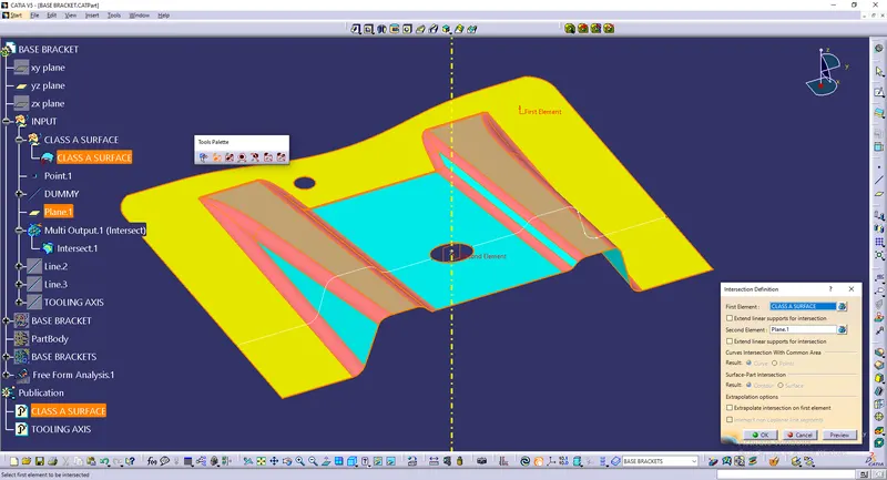
The lines which are perpendicular to the dummy axis may pass the creteria in the Draft analysis so the work is to be done with the parallel lines from the intersection taken. So A line is drawn on the parallel lines.
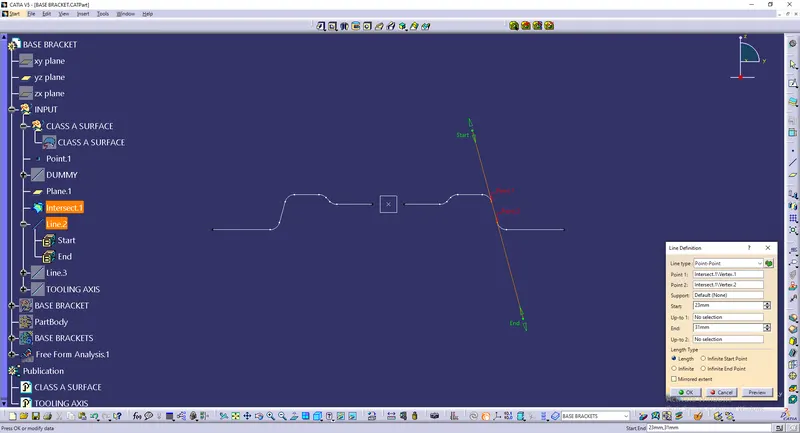
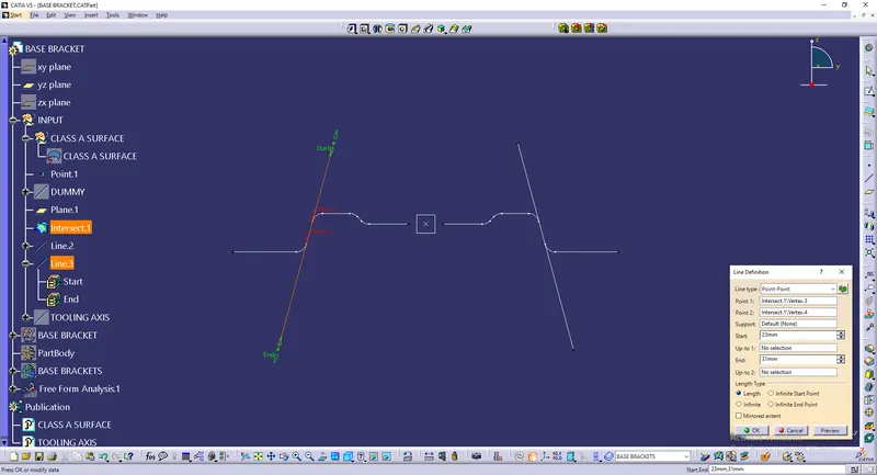
A bisecting line is taken for both the lines drawn above.

This line is the TOOLING AXIS.
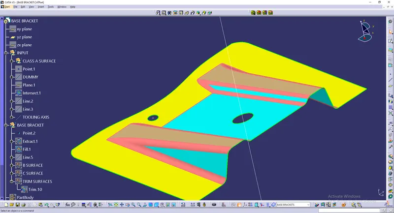
The boundary of the hole in the Class A surface can been extracted using Boundary command and a ppoint is created and the axis for the hole alone is drawn. In further steps whike creating Class C surface. It'll be helpful by the sweeping the extracted boundary with the respect to the axis drawn.
A point is created.
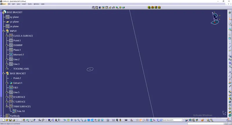
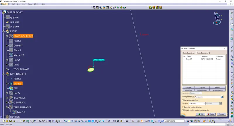
Fill option is used to close the hole.
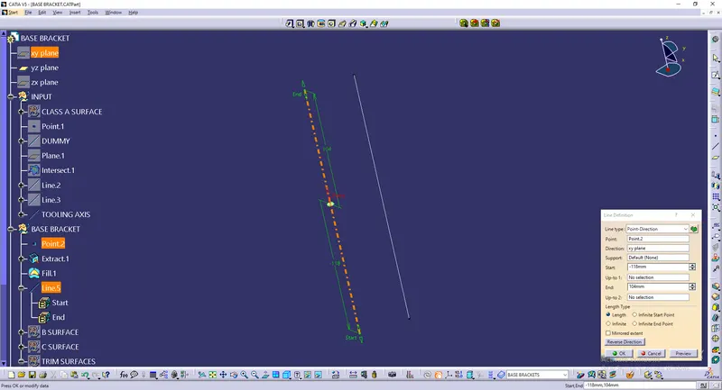
A center axis for the hole is created.
RIBS:
(Rib 1) Ribs have been extracted from the Class A surface.
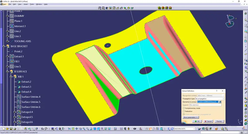
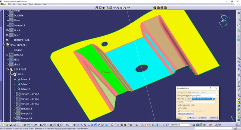
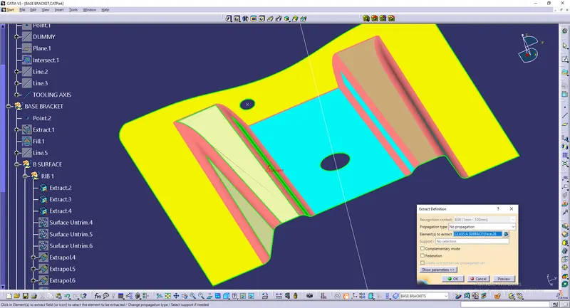
These extracted surfaces are Untrimed using surface untrim.
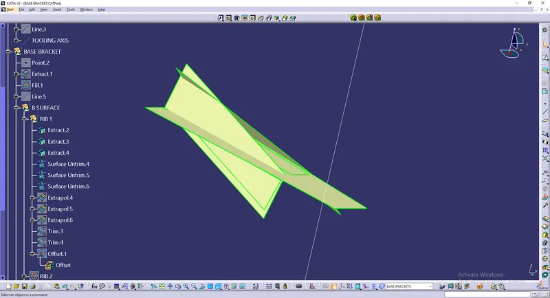
And they are further extrapolated to certain distance that they intersect with each other.
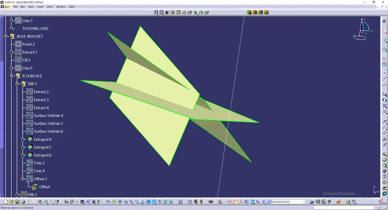
Using Trim command, these extrapols are triimmed to get the rib structure.
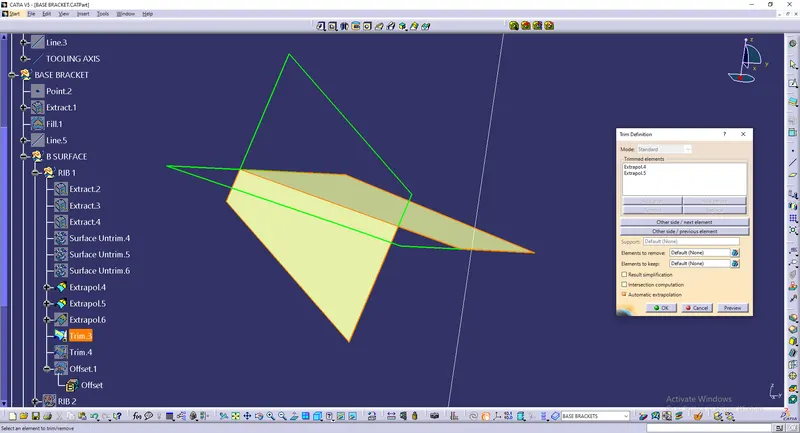
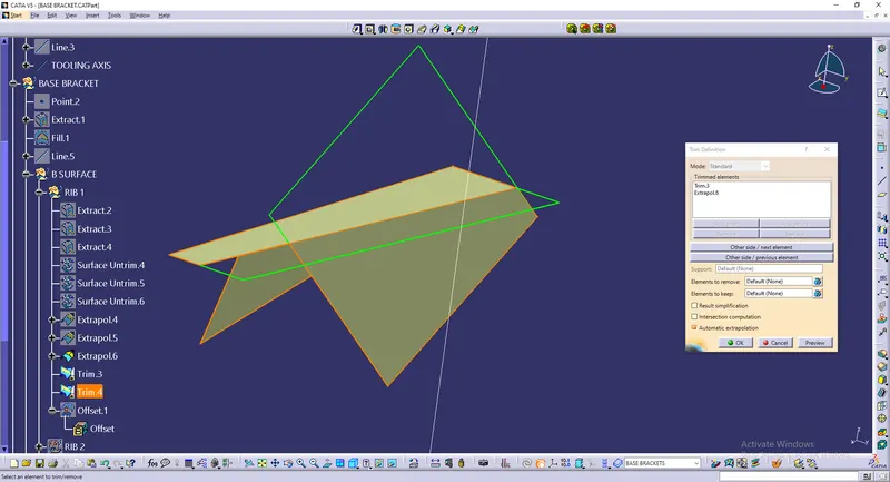
A rib like structure is obtained and that surface is then offsetted to 2.5mm distance.
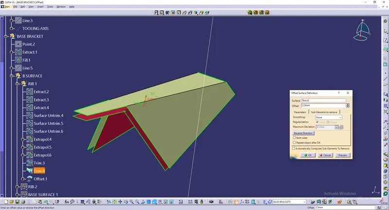
The same steps are followed for the RIB 2 surface from the Class A surface.
Rib extraction
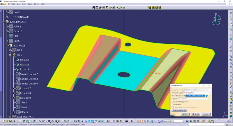
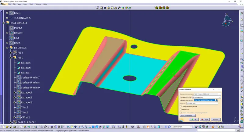
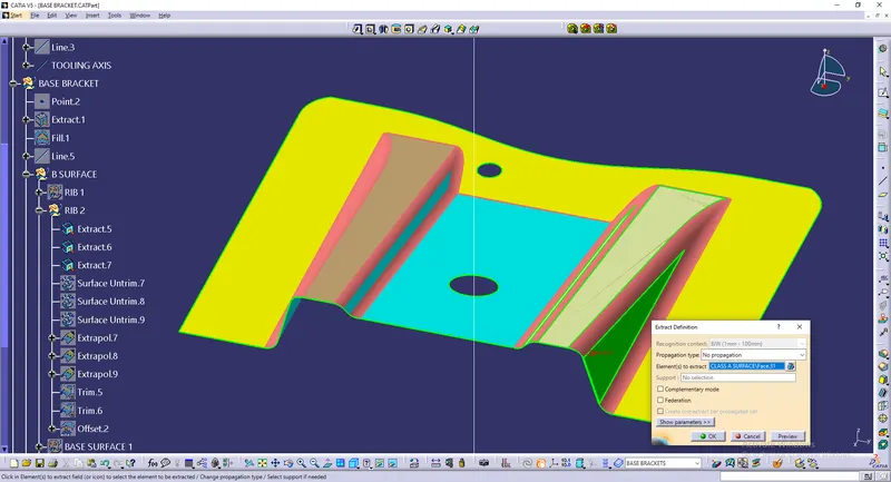
Surface Untrim
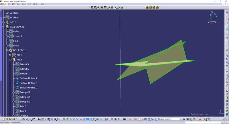
Extrapols
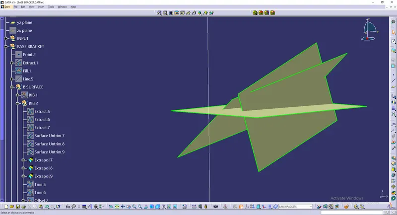
Trim
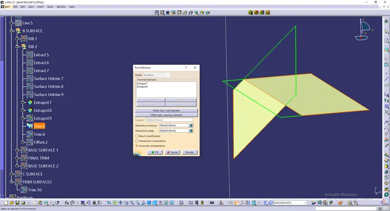
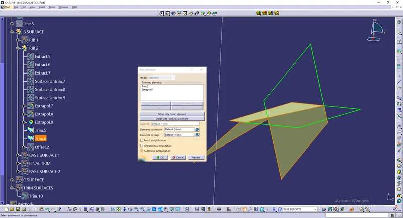
Offset
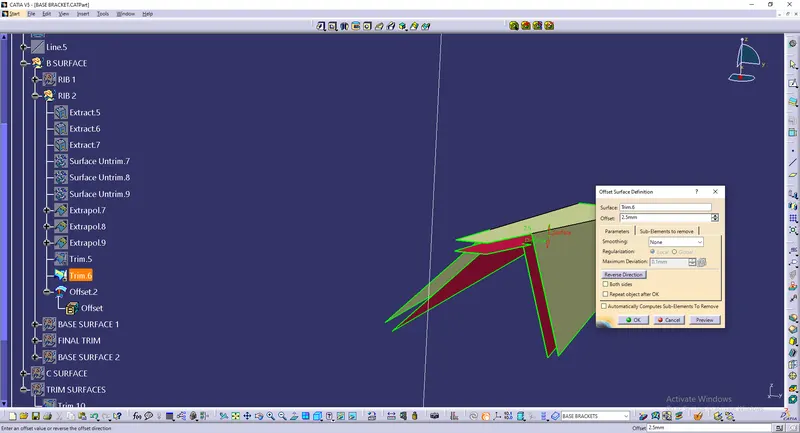
BASE 1:
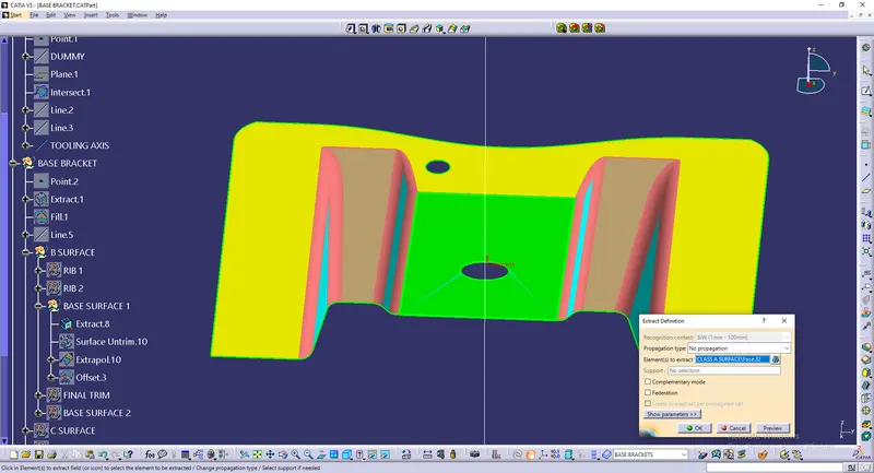
The Base surface is extracted from the Class A surface
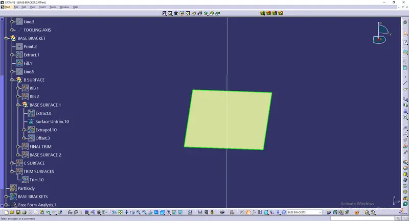
The extracted surface has been untrimmed using surface untrim
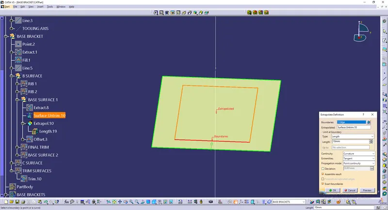
The untrimmed surface is extrapolated to length of 10mm.
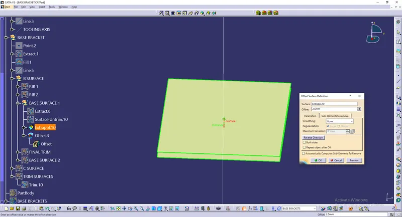
It is offsetted to 2.5mm distance.
Both the trimmed Ribs surfaces and the Base surface is to the trimmed together.
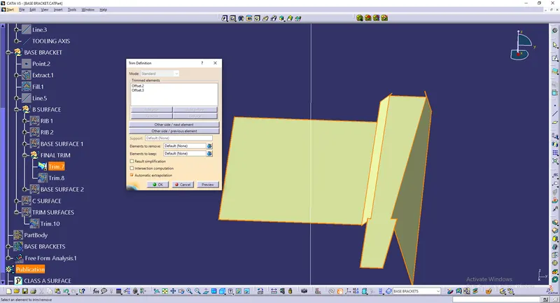

BASE 2
2nd Base surface is extracted from the Class A surface
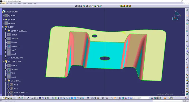
The extracted surface is then untrimmed using Surface untrim
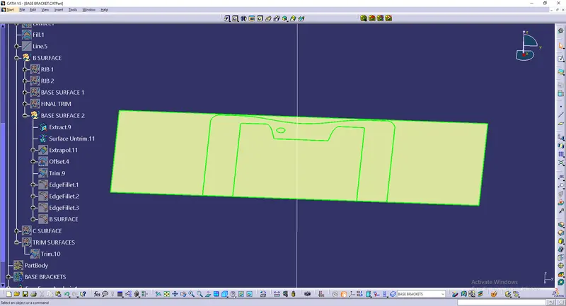
The untrimmed surface is extrapolated using extrapol command.
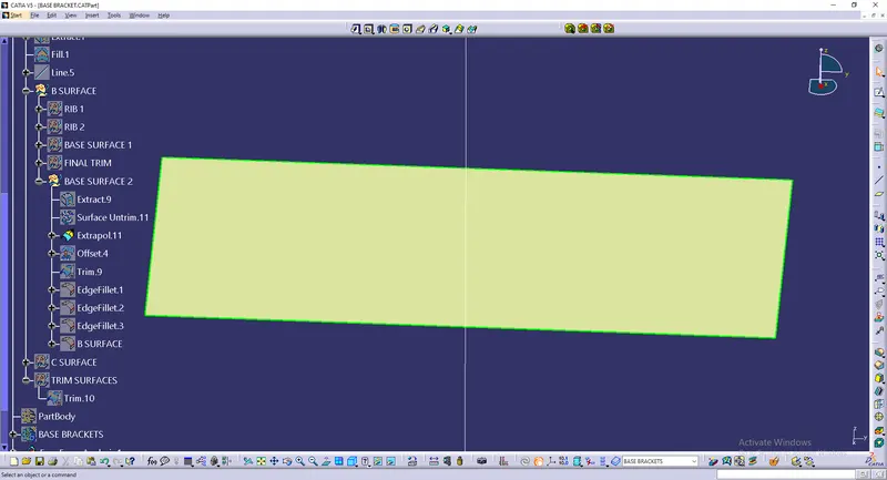
The extrapolated surface is offset to 2.5mm distance.
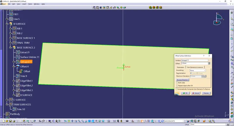
This offseted surface has been trimmed with the already trimmed surfaces.
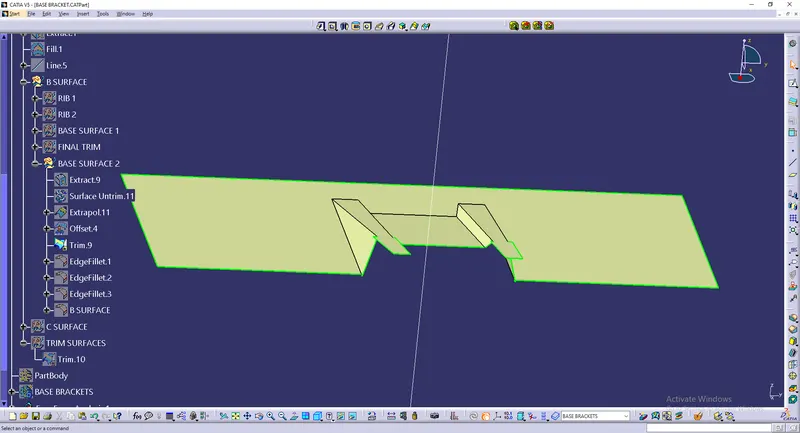
The edges are filleted based on the Class A surface.
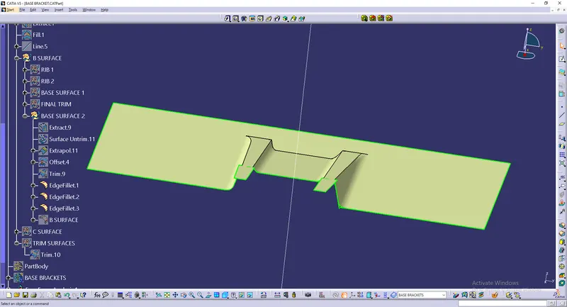
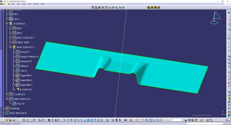
Thus Class B surface is created.
Class C surface
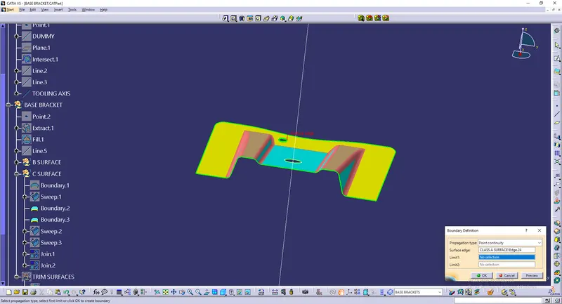
The boundary of the Class A surface is extracted, to create the Class C surface.
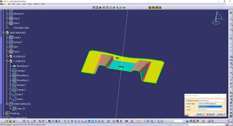
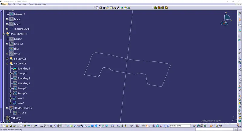
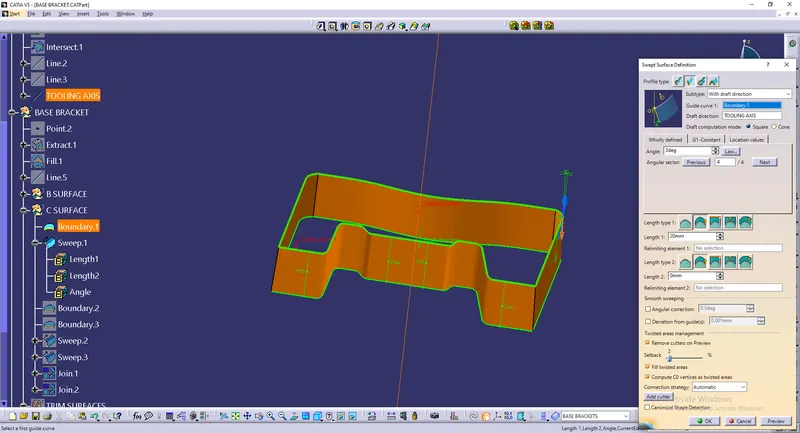
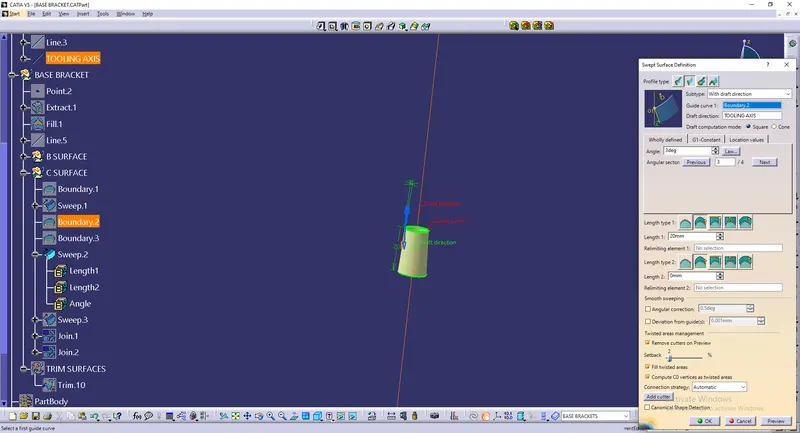
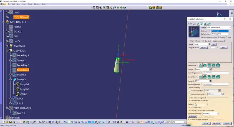
This extracted boundary is sweeped with the draft of 3deg away from the Tooling axis.
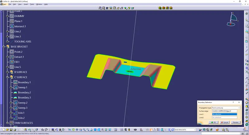
There are two holes in the Class A surface, their boundaries are too extracted and sweeping is done.
Boundary extraction
Sweep
The sweep surface of the Class A and Class A surface is joined together using Join command.
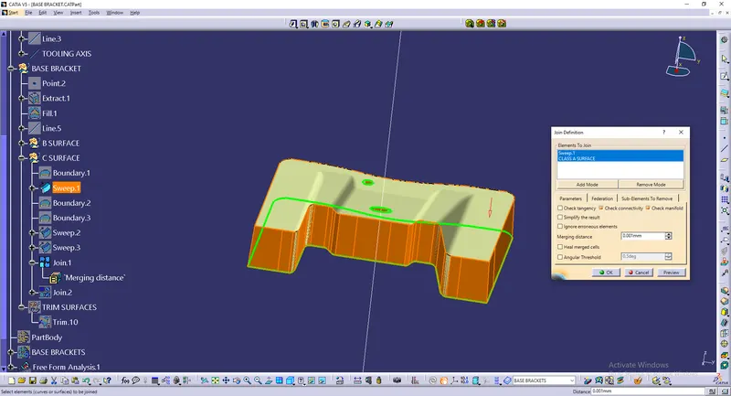
The above joined surfaces and the sweeped surface of the holes are joined together.
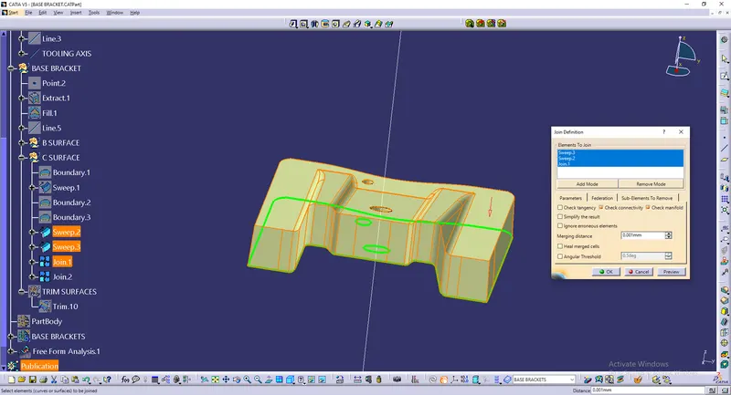
Now all these joined surfaces (Class A surface and Class C surface) is trimmed with the Class B surface.
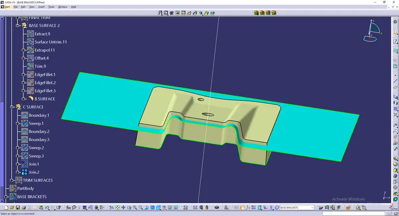
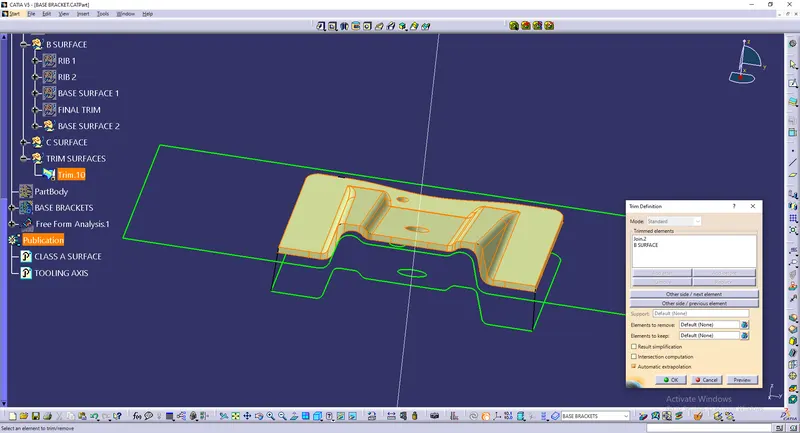
Solid
This trimmed surfaces are made into solid with the help of Closed surfaces command.
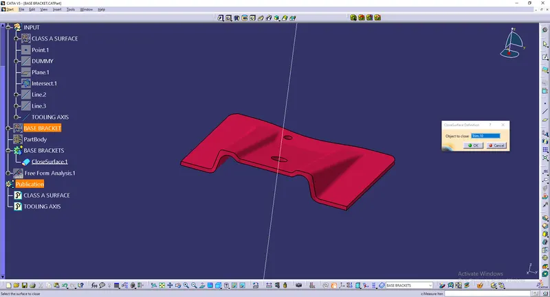
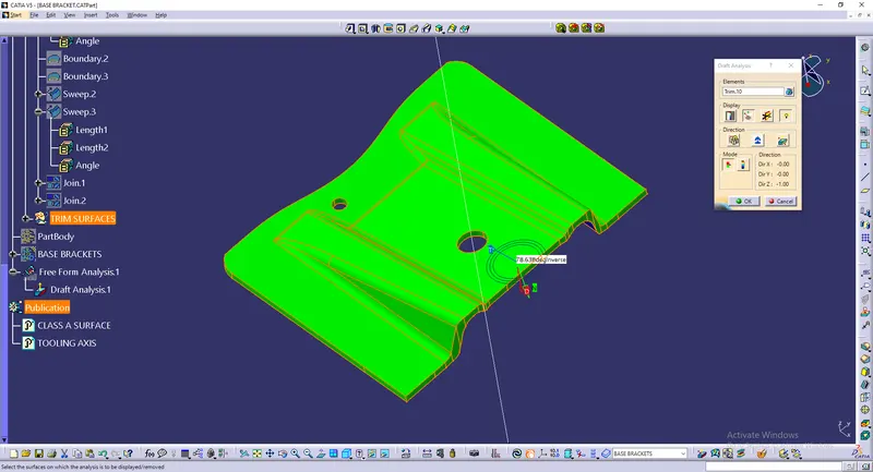
DRAFT ANALYSIS
Draft analysis is done for the model.
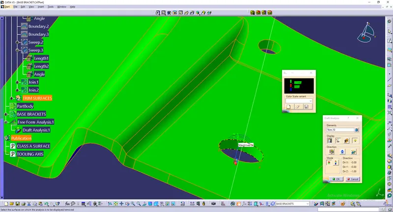
The surfaces with minimum of 2.5deg draft shows green color other than that shows blue and red shows with doesnt pass 0deg. the Tooling axis is made as the axis with which the draft will be analysed.
Front view
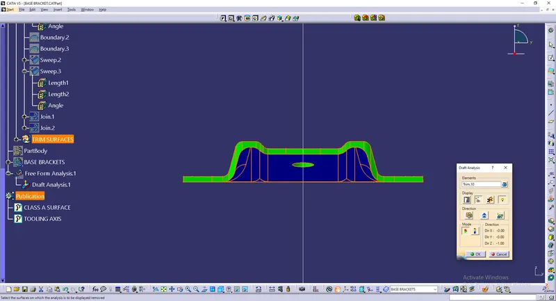
Side view
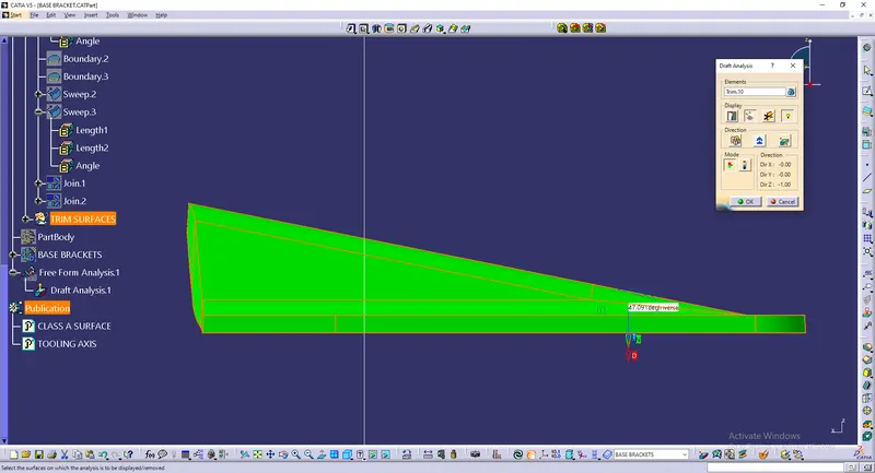
Top view
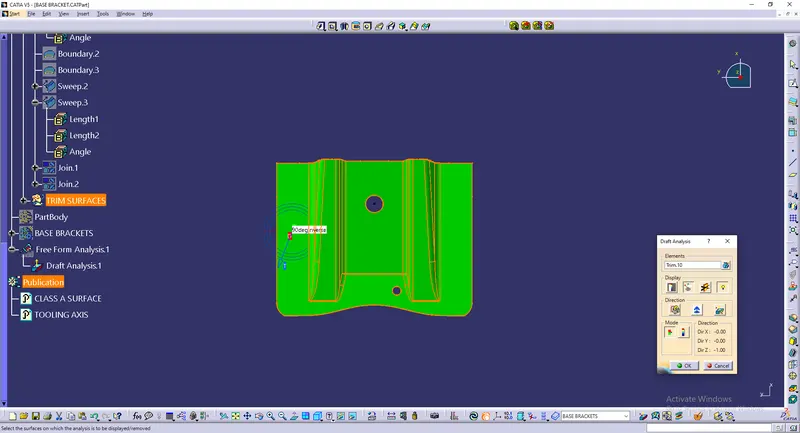
Isometeric view