Week 8 - Challenge 2 - Base Bracket Design
AIM:
To Create the Base Bracket Plastic component through the given Class-A surface. To begin with, the tooling axis for the given Class-A Surface should be created meeting the requirements of the draft angle and at the end perform the Draft analysis on the model.
PROCEDURE:
- It is a Base bracket that we are going to check the draft angle on this product.
- Initially the connectivity of the class A product should be check by using join and it has ensured that no surface gap inbetween it, it can also be checked in visual.
- By using the boundary option the boundry line will be created around the surface of the product.
- Then it must be disassambled and the connectivity of the surface must be checked.
- Then in all directions that sholud be checked for the perfect tooling axis that in which direction the tooling axis is good to view.
- In this particular product Z would be the best possilble tooling axis.
- For creating a tooling axis the new geometrical set has to be created, in that geometrical set the origin point must be fixed initially then the axis system is placed on that origin point.
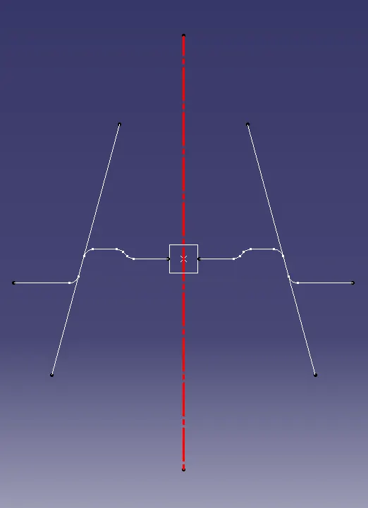
- Then by taking the ZX plane the intersection will be done with respect to the Base bracket and as a result there will two lines are projected the intersection line that is shown on the picture below.
- Before creating the original tooling axis the dummy tooling axis is created which is perendicular to the intersection line.
- The Bisecting line has to be created with the help of line command initially the point to point line is used to create two lines after that by using that two lines the bisecting line is also created by connecting the origin point.
- That bisecting line is Tooling axis for X direction and it is renamed as Tooling direction of X axis.
- By having X tooling axis the tooling axis of the Base bracket is created.
- Then the tooling axis and fan cover is projected for viewing easily.
- It is the Class A surface of the base bracket.
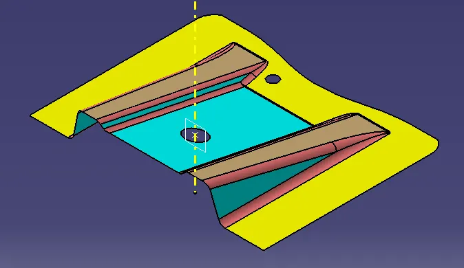
- The publication of the Base bracket and tooling axis has to be done for the easy access.
- Then opening the draft analysis tool bar which is in the Tools.
- In the draft analysis toolbar the campus symbol which is there has to be picked and then red point on the campus can be moved to the toolingaxis in the perfect alignment, that campus is used to denote the draft direction.
- Then the surface of the ribs are created and it is trimmed according to the rib size.
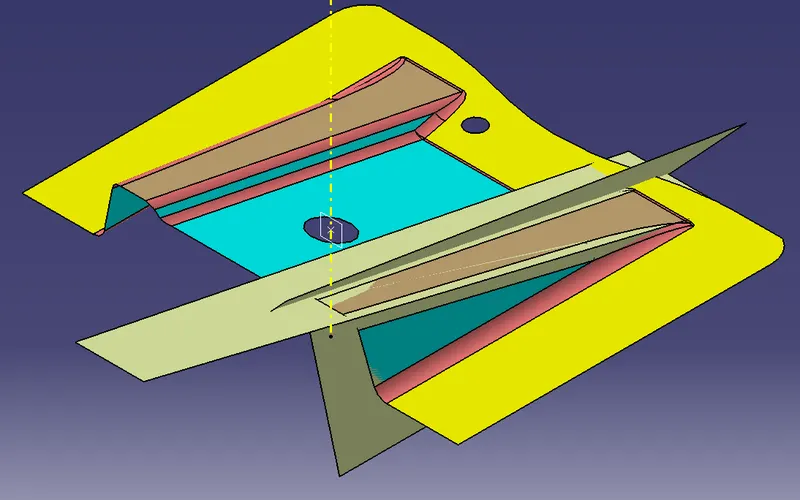
- Then the b surface will be fully created and the fillet on the A surface will be filleted on the B surface with fillet size of fillet radius and the thickness of base bracket.
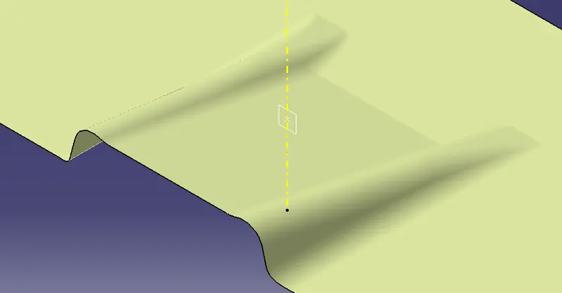
- The C surface will be created by projecting the boundary lines.
- By using that boundary lines the C surface will be created this can be trimed by the B surface that already created.
- The C surface that are created will be on 2.5mm height.
- There are two circles on the base bracket for that also boundary has to be created and C surface will be extruted inward upto 2.5mm
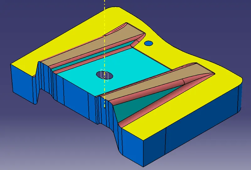
- Then the C surface will be trimmed with respect to the b surface that is created.
- After that every surface should be joined by using the join command.
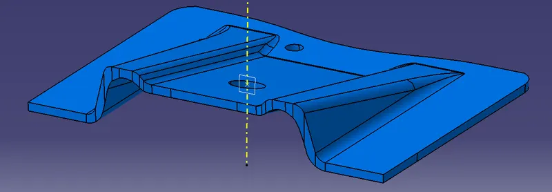
- The Draft analysis of the Base bracket is shown below.
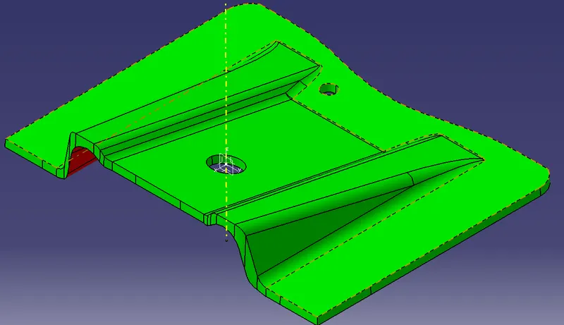
- The surface that is created will be changed into pert model for converting it into the closed part.
- So that there will not be any open area on the Base bracket.
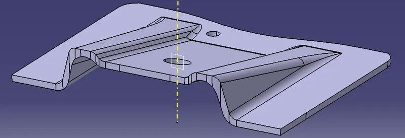
The Draft analysis of the Base bracket is shown below.
RESULT:
Hence the Draft angle has been analysed on the Base bracket which can able to design and the Base Bracket Plastic component through the given Class-A surface has been created.