Week 8 - Challenge 2 - Base Bracket Design
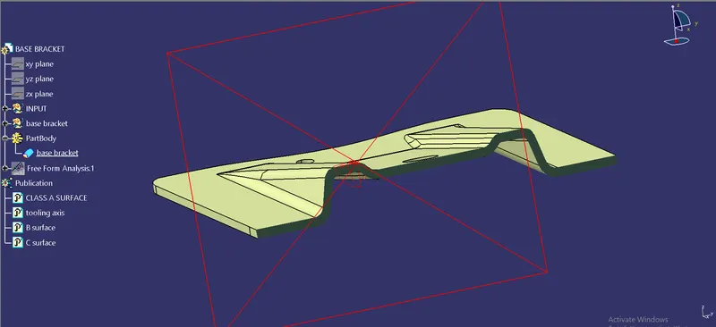
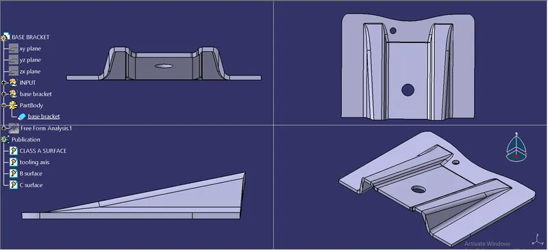
Creating of tooling axis and Class B and C surface from the given class A surface of the base bracket and making a solid body:
Tooling axis and Draft analysis:
The given surface model is downloaded and opened.
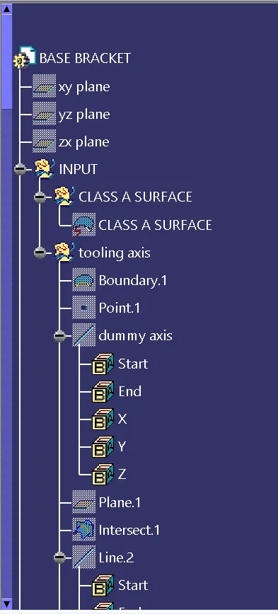
Then a boundary line is created by selecting the model.
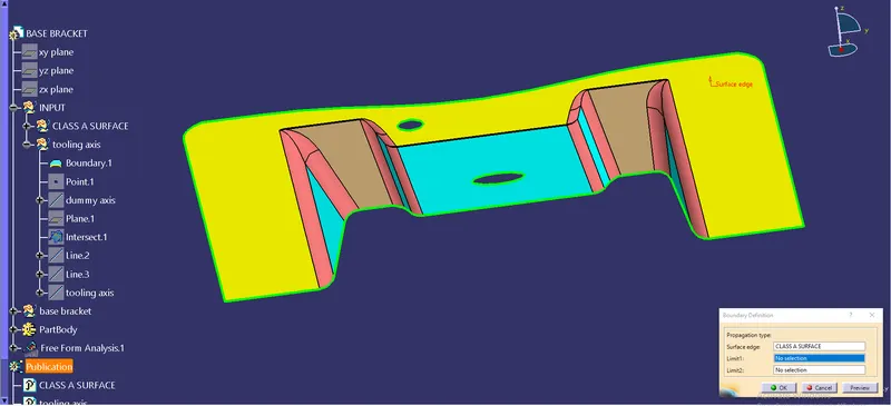
After creating the boundary line, the model is analysed visually and created a point with the top circle as reference. Then a dummy axis is created with the idea from the visual analysis.
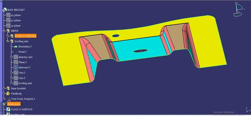
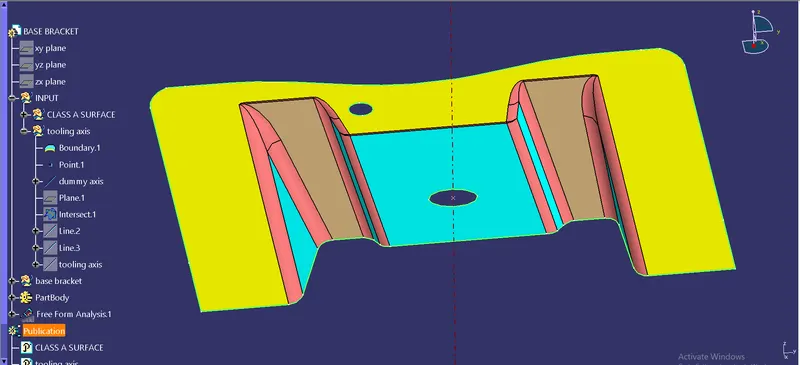
After creating a dummy axis an yz faced plane is created on the point and with dummy axis. Then the model is intersected and an outline of the model has been created in that plane.
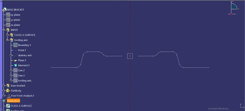
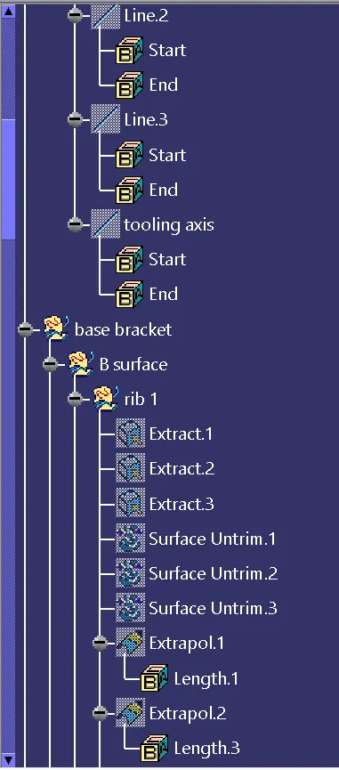
Then two lines are drawn along the both the sides of the model which is inclined. A line is drawn on the point created before which has the bisecting with the line reference to the line created.
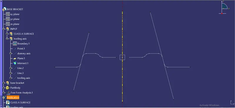
That bisected line is setted as the tooling axis.
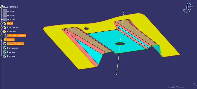
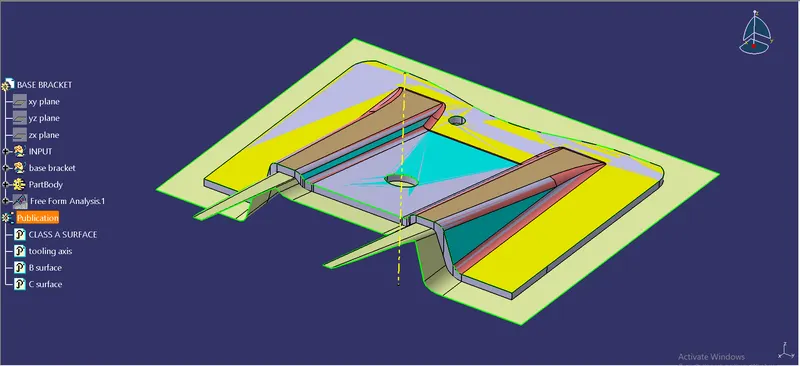
Keeping that line as the tooling axis, the compass is placed in that line and locked the draft direction through that line. And the draft is analyzed successfully.
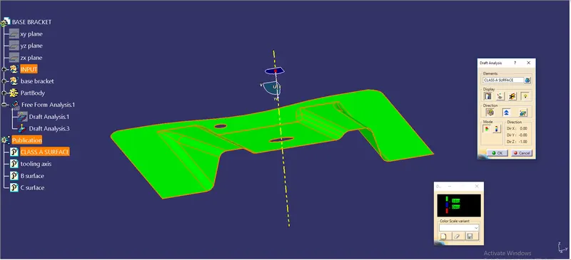
Creating B surface:
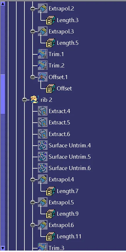
After analysis, the B surface is started. The 1st rib is created by extracting the 3 surface of the rib, Then the exracted surface is extrapolated after untrimming it.
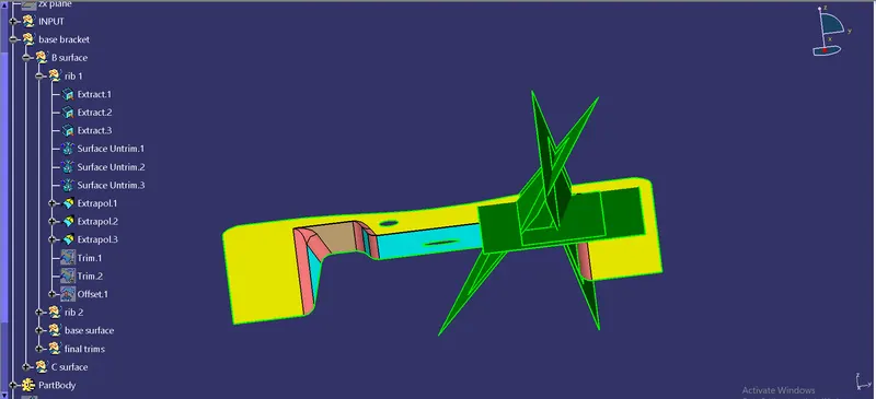
Then the extrapolated surface is then trimed to form the shape and it is offseted to 2.5mm.
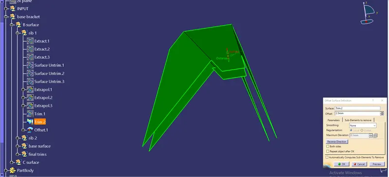
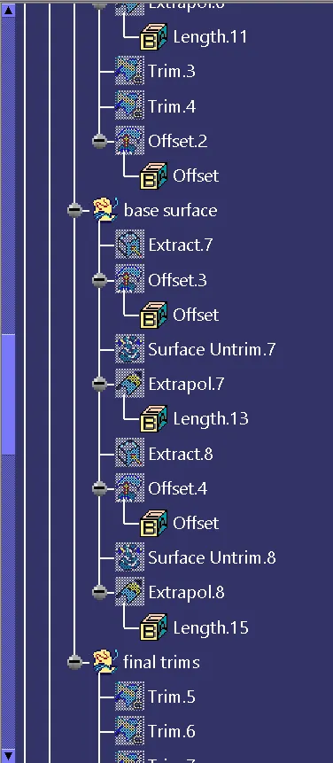
Similarly the 2nd rib is also crearted by the same procedure of extracting untrimming extrapolating trimingt and offseting.
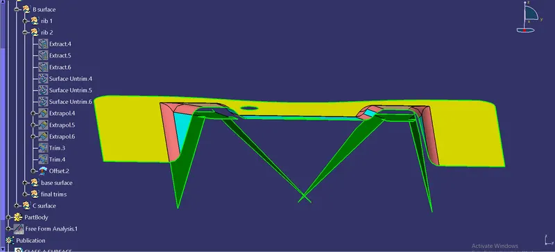
These same procedure is also carried out to form the base surfaces.
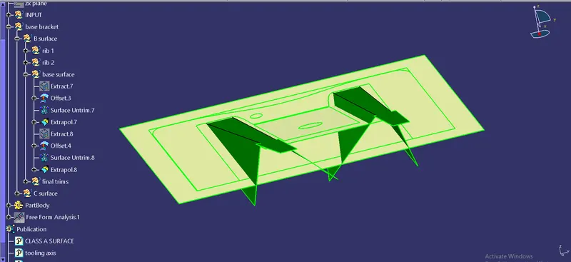
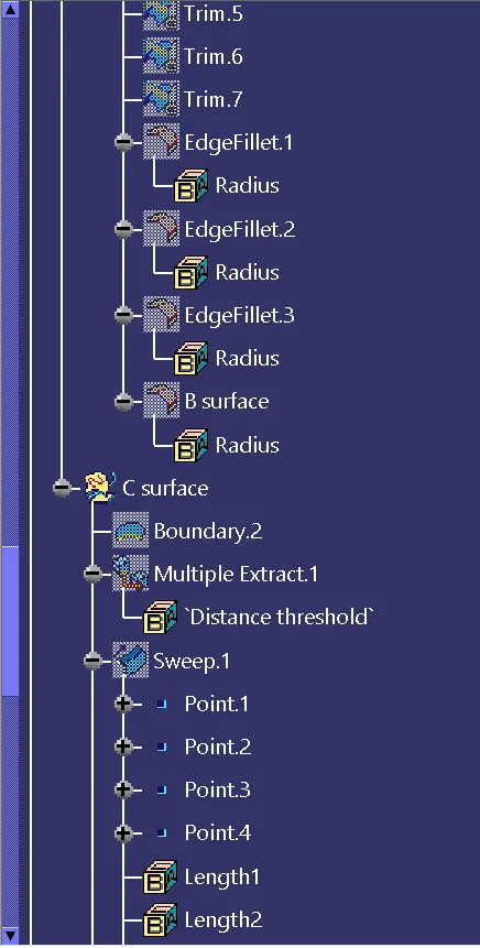
Then all the offsetted surfaces are trimed to from the base bracket shape at an offset of 2.5mm and filleted.
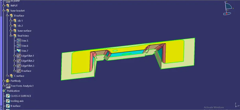
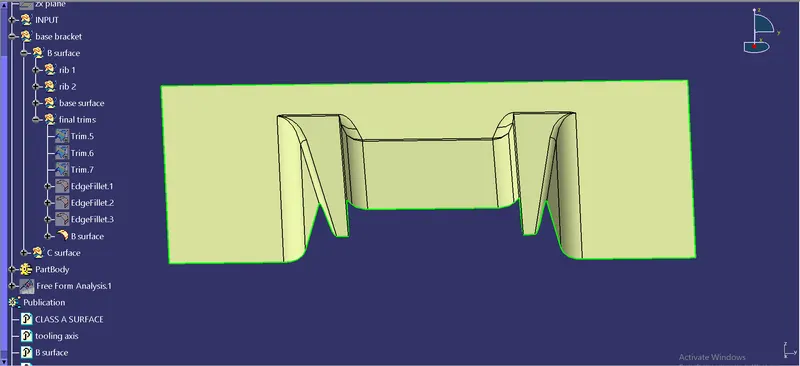
Creating C surface:
To create the C surface, first the boundary of the A surface is been created as a line. From that the outer line is extracted to an individual set.
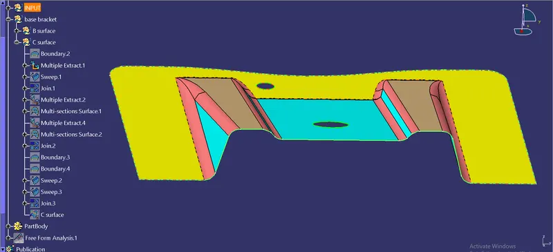
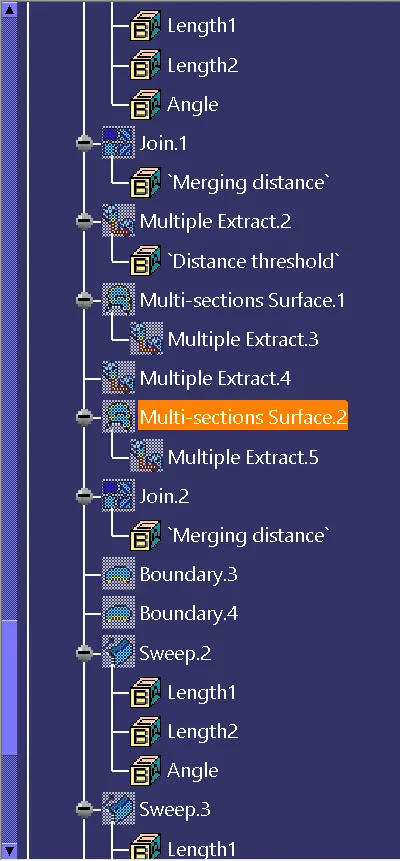
Sweep command is used to create surface for the C surface. The outer line is selected and sweeped along the tooling axis with a draft angle of 3 degree. Limit is used as it showed an error. And then the surfaces are joined to from as one.
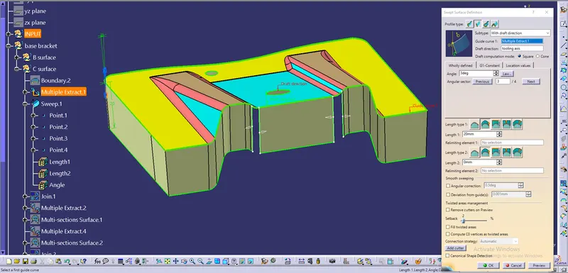
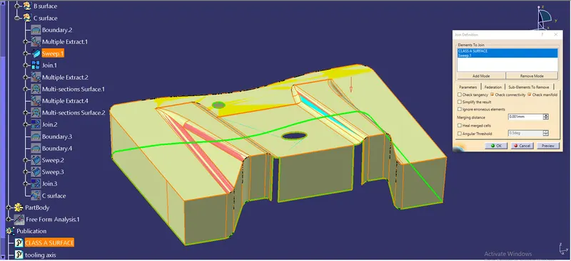
To complete the surface, the boundary line is been extracted.
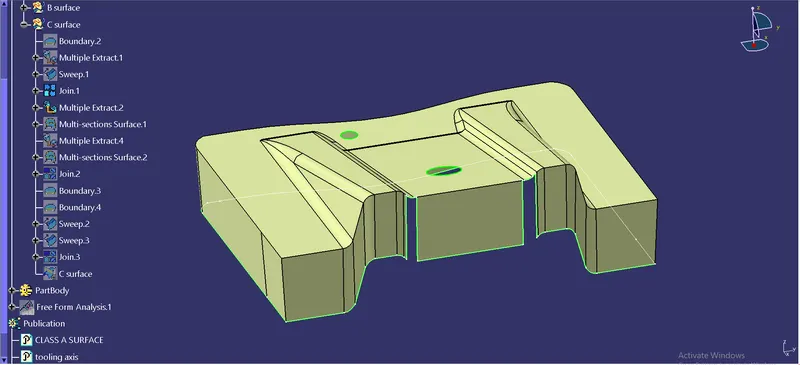
And the missed part is been filled by the multi section surface.
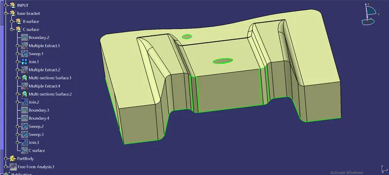
This same procedure is been used to form the sweep for the hole on the top.
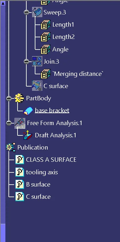
Then all the sweeped surfaces are been joined to one surface.
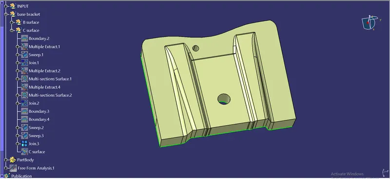
.
After joining the created surface, This joined surface is then trimed with the B surface to form a closed surface.
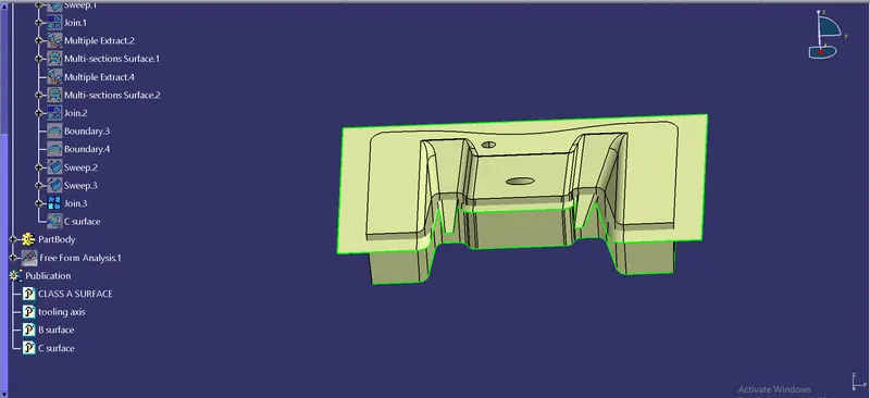
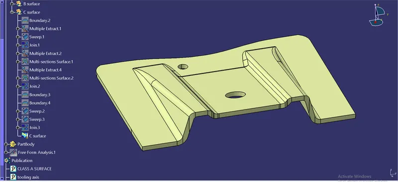
After the creation of the closed C surface, it is then filled and made to a solid part.