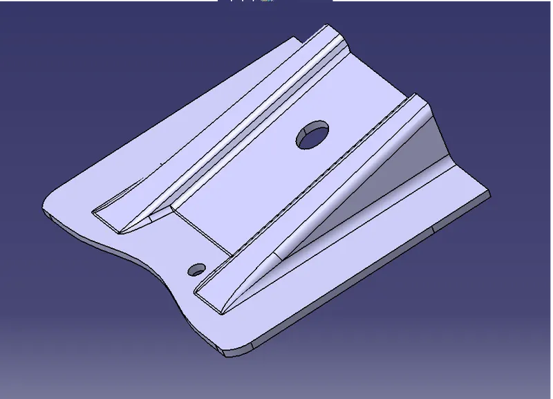
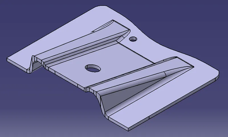
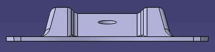
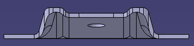
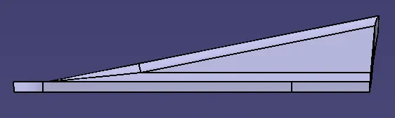
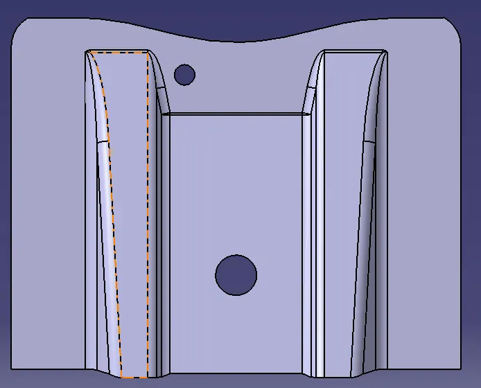
Week 8 - Challenge 2 - Base Bracket Design
MODEL 1
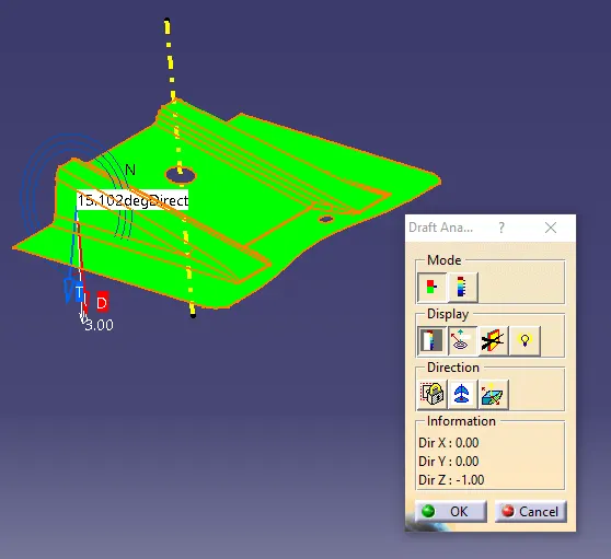
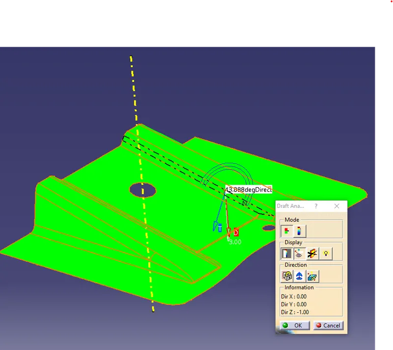
DRAFT ANALYSIS
- Tooling axis is to be determined by checking x, y and z direction of tooling axis.
- The best suited axis is taken, in this case z axis is taken
- A dummy tooling axis is made at the hole on the base bracket
- The problamatic area for draft is checked and a intersection line is created
- 2 lines are created on the angle of the draft present and a bisecting line is created with the 2 lines
- This bisecting line is the drafting axis
- Draft analysis is done based on this tooling axis
- The green colour represents the draft angle is within the required limit
CREATING CLOSED SURFACE
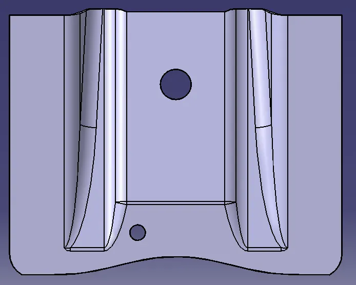
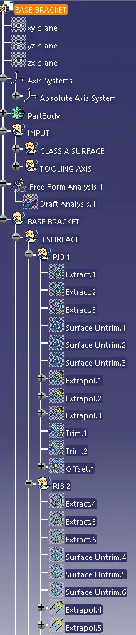
- WIth the given Class A Surface, Class B Surface is created
- First, the required surface is extracted
- Then the extracted surface is untrimmed and extrapolated with Continuity for curvature and Point continuity for Propogation mode
- This surface is offsetted for the required thickness, in this case 2.5mm
- The remaining surfaces are trimmed
- Edge fillet of 5.5 mm is used for the edges as 3mm is the required and thickness of 2.5mm gap is added to give 5.5mm edge fillet
- The Class B surface is created
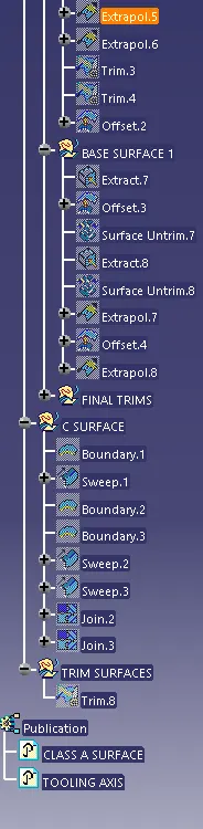
- The closing of Class A and Class B surface created Class C Surface
- This is done using Sweep commmand
- The line sweep is selected
- Subtype is chenaged to Draft Direction, The Class A boundry is selected for guide curve and Tooling axis is selected for Draft direction
- Standard option is selected for both Length type 1 and 2
- Now, the desgin is changed to Part design for closed surface option