Week 8 - Challenge 2 - Base Bracket Design
Aim :
To create the Base Bracket Plastic component through the given Class-A surface with the tooling axis for the given Class-A Surface should be created meeting the requirements of the draft angle and at the end perform the Draft analysis on the model.
Creation of Tooling Axis
Here first we have to create a tooling axis with respect to point and axis system in the upper surface hole of given Class A surface. Tooling axis is created by bisecting the lines of X axis tooling and y axis tooling axis .
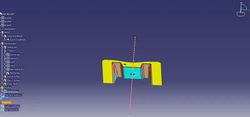
Draft Analysis
By using tooling axis, we analysed draft angle in the face of Class A surface. If the drat angle is less than 3 degree it will shown like error like variation of colors.
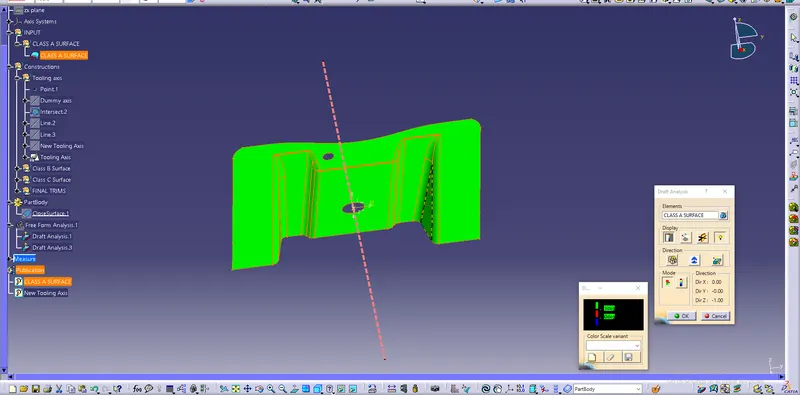
Class A Surface :
we have extracted class A surface from the input and used that surface to create a new part body.
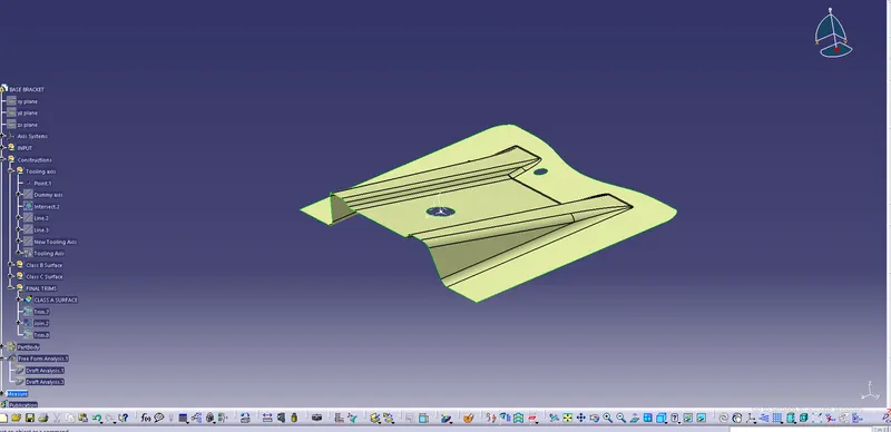
Class B Surface
From Class A Surface,all sides are extracted, untrimmed, extrapolated, offsetted and trimmed the parts to create B surface and named it . Actually B Surface is the Bottom face of the part which drafted 3 degrees in standards. Those should be created in separate geometrical sets .
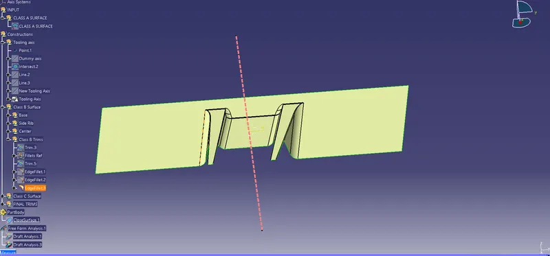
Class C Surface
In C Surface, we creaste and boundaries from th A Surface and changed to smoothened using smooth curve tool. Then we sweep the curve in the angle 3 degree with respect to tooling axis direction.
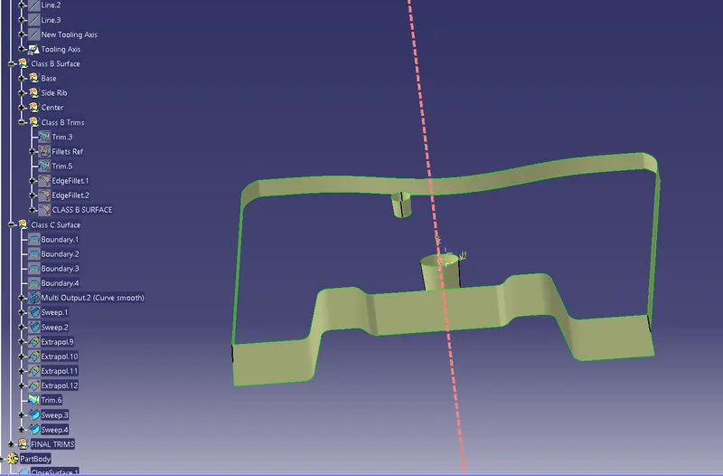
Class A and Class C joining.
Now a new geometrical set is created for final operations where Class A and Class C surfaces are defined and trimmed. This will join the surfaces into a single one. In other case like creating a new class A surface from the input class A surface it requires trimming, thus it will join the surfaces.
After Creation of A,B and C Surfaces
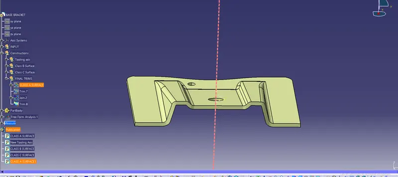
Part forming
In this step the work bench is changed to Part workbench , where closed surface option or tool is used to finish the surface model into part body.
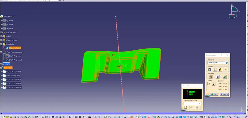
Draft Analysis
Draft analysis for the part body is performed. This is to check whether the part it has the required draft angle according to the industrial standard of 3 or more degrees.
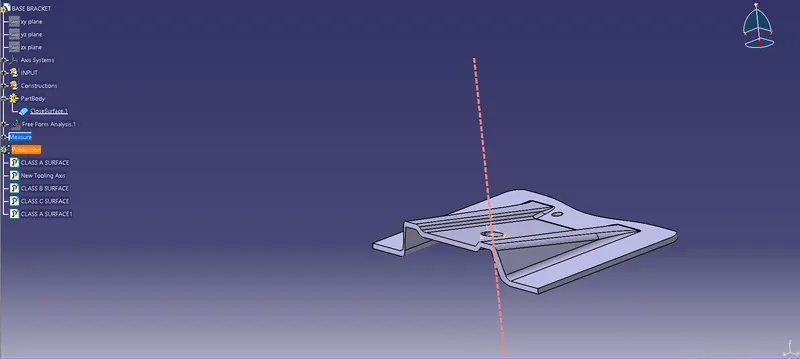
Isometric and Orthograpic view of Base Bracket model
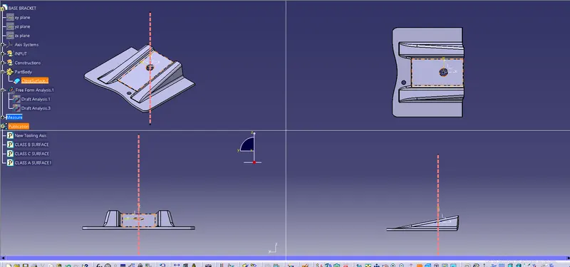
Publication :
By using Publication Tool, published Tooling axis and Class A,B and C Surfaces.
Conclusion
From the Given Class A Surface of Base Bracket, created the Plastic component and analised the draft angle with respect to the tooling axis and used close surface tool change into the part model.