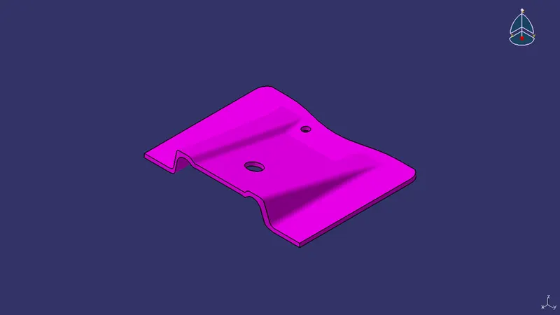
Week 8 - Challenge 2 - Base Bracket Design
Draft Analysis:
Draft analysis is a technique used to analyze whether the part model created in CAD is manufacturable based on the draft condition. We are providing the tooling direction or the direction in which the component should ejected in order to get an easy removal of the component. It also let us know the draft angle of the model from the tool direction. For plastic components the ideal draft angle ranges from 0.5-3.0 degrees.
Procedure to do Draft analysis on Base Bracket using CATIA V5:
Visual Analysis:
- Initially the product must be checked for any open surface in it. It can be checked by using the join operation or Boundary operation.
- Then the direction for tooling is determined.
Creation of Tooling Axis or Direction:
- Once the appropriate direction is chosen (for Base Bracket it is Z direction), then a point is created on the center of the hole found in the part.
- Then a line is created on the point along Z direction. This would be the dummy tooling axis.
a) Tooling axis along X direction:
- Axis system is placed on the point to create the intersection on the Base Bracket. Intersection of the part is created on the zx plane.
- Two lines on either sides are created on the points of the curve, which is available on the intersection.
- Then a Bisecting line is created using these two lines and the point, which will be the Tooling axis along X direction.
b) Tooling axis along Y direction:
- Intersection of the part is created on the zy plane.
- Two lines on either sides are created on the points of the curve, which is available on the intersection.
- Then a Bisecting line is created using these two lines and the point, which will be the Tooling axis along Y direction.
Draft Analysis on Base Bracket:
Step 1:
We need to change the view parameter to custom view and select “Material ” option under Mesh.
Step 2:
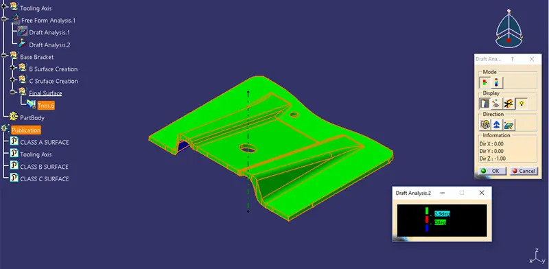
- Go to Insert > Analysis > Feature Draft Analysis or click on the “Draft analysis icon
 ”.
”. - Draft analysis dialogue boxes will appear. One containing different colors and angles.
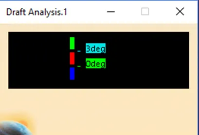
Another containing different options to use.
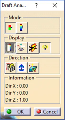
- Click on “Compass icon
 ”to insert a compass on our part. It will be inserted on Origin point. Then try to drag the compass and place it on our part roughly.
 - Then the compass can be placed on the Tooling axis and locked using the “Lock” icon on the dialog box.
- Modify the draft angle beside the Green color to ideal draft angle “3 degree”
- Click anywhere on the part and it will change into green color. If not try to modify the part.
Publication:
After completing the Draft analysis, Tooling axis and the Class A surface can be published to spot and access them easily.
Draft Analysis of Base Bracket Class A surface:
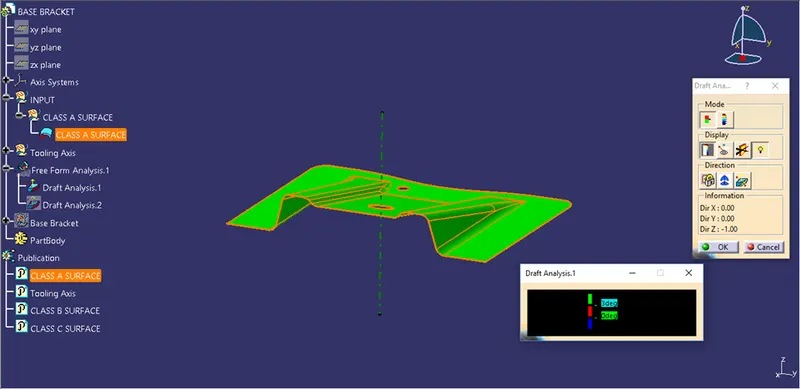
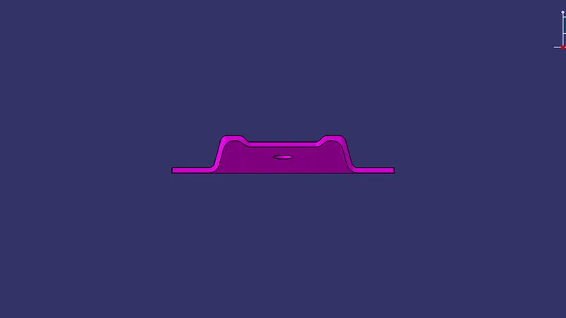
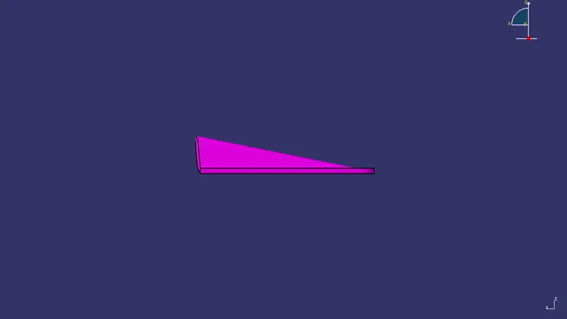
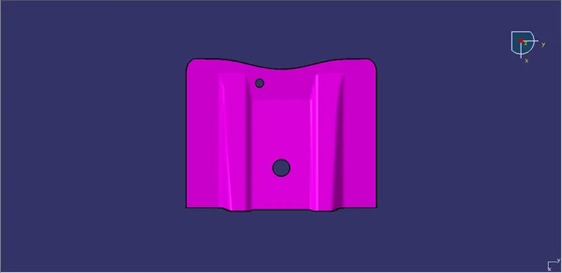
Draft Analysis of Base Bracket final plastic component: