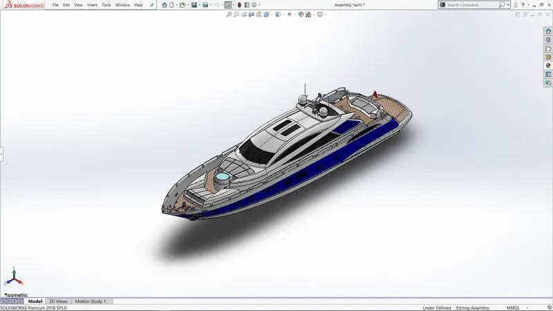
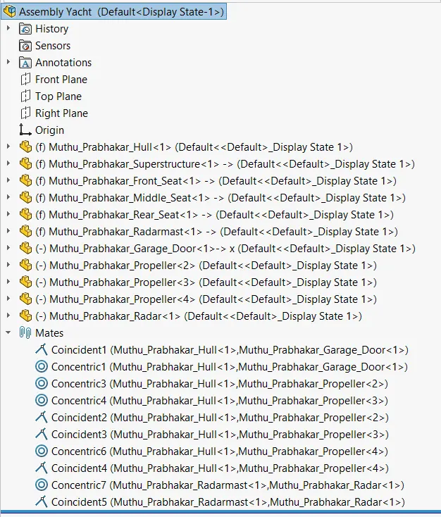
Radar Mast & Final Assembly of Yacht
Modelling of Sunseeker Predator Yacht on Solidworks
Introduction:
In this course, we learned about complete designing of Sunseeker Predator Yacht using solidworks, from the initial sketching to the final assembling. With the help of appropriate dimensions, sketching of all the parts were done and created separately. Once every part is created, then we assemble the parts into a complete model. After assembling the parts, addition of decals, lights and camera etc. is done to do the rendering of the Sunseeker Predator Yacht using Solidworks visualize.
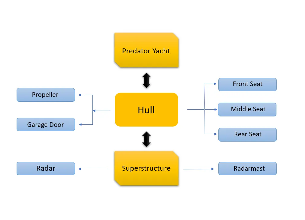
The parts or the components we created to make the Sunseeker Predator Yacht are:
- Hull.
- Propeller.
- Radar.
- Front Seat.
- Middle Seat.
- Rear Seat.
- Garage Door.
- Radarmast.
- Superstructure.
Objectives:
- To Sketch the parts of Sunseeker Predator Yacht using solidworks.
- To Assemble all the parts to make a complete model in solidworks.
- To add decals and to set camera and lights to get a realistic view of our model.
- To render the model using various features available in the Solidworks visualize.
Design Approach:
There are two types of design approach we follow in designing.
Bottom-up approach
Top-down approach
Bottom-up approach: In the bottom-up approach, the most primitive operation is done first followed by the complex operations.
Top-down approach: The approach in which the design is started at highest possible level and the sublevels are followed by it.
Features / tools used to sketch and design in solidworks:
We have,
- Extruded Boss/Base
- Revolved boss/base
- Extruded Cut
- Extruded Surface
- Swept surface
- Revolved Surface
- Loft Boundary
- Fill surface
- Ruled Surface
- Trim Surface
- Knit Surface
- Fillet
- Chamfer
- Linear pattern
- Knit
- Plane
- Projected Curve


Fig. 01. Features Tab
Extruded Boss/Base:
Extruded boss/base feature is used to make a sketch into a complete solid model or part. This feature contains option such as “From to Direction” to select the direction in which we want to extrude our part. “Dimension” column to get the required the length of our model.
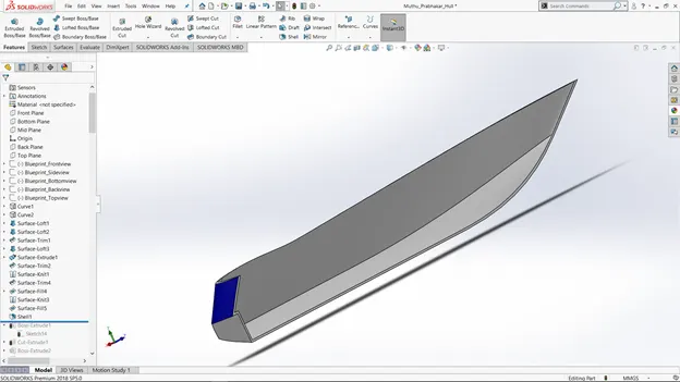
Fig. 02: Model before applying Extrude Boss/Base feature.
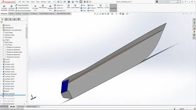
Fig. 03: Model after applying Extrude Boss/Base feature.
Revolved Boss/Base:
To get a cylindrical object, we use Revolved Boss/Base feature in our fully defined sketch. As in Extruded Boss/Base feature we got “Axis of Revolution” to give the axis or plane in which we wish our model to revolve. We also got the direction tab to give the direction for our model.
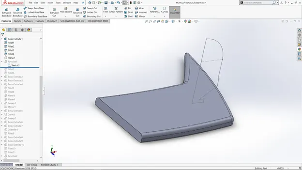
Fig. 04: Revolved boss/base feature before applying.
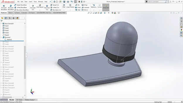
Fig. 05: Revolve boss/base feature after applying.
Extruded Cut:
If we want a hollow space in our model, we can do it by using the Extruded cut feature. This feature requires a proper fully defined sketch with closed entities. When we click on this feature, the property manager window will pop-up with an option similar to Extruded boss/base feature. It got “From and To” to give the feature from where it has to cut our model. And the direction in which it has to cut is given in the “Direction” section available.
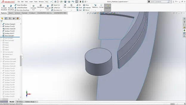
Fig. 06: Extruded Cut feature before applying.
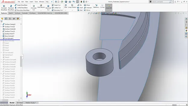
Fig. 07: Model after applying extruded cut.
Extruded surface:
Extruded Surface feature is used to create an extruded surface of the sketch. Unlike Extruded Boss/Base, Extruded surface feature creates a surface which is not a closed one.
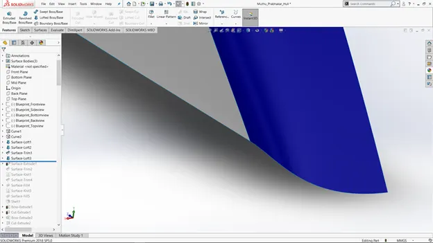
Fig. 08: Model before applying Extruded Surface.
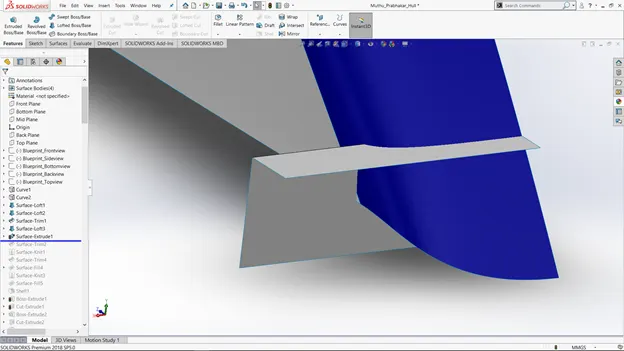
Fig. 09: Model after applying Extruded Surface.
Fillet:
Fillets are the most important and frequently used features in making a model as it has got many advantages. Once we made a solid part, it will have sharp corners and edges which we do not like to have. So, to make the sharp edges/corners to look smooth and have nice finish, we use this “Fillet” feature. The thickness of the fillet can be adjusted in the property manager window pop-up.
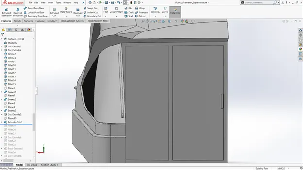
Fig. 10: Model before applying fillet feature.
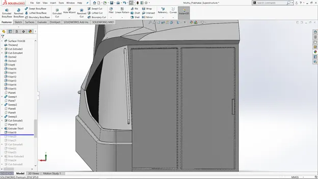
Fig. 11: Model after applying fillet feature.
Linear Pattern:
Linear pattern is used make a copies/duplicates of the feature which we want in our model, in the linear direction. It is an easy feature which let us do same the process for n number of times, without adding any extra sketches.
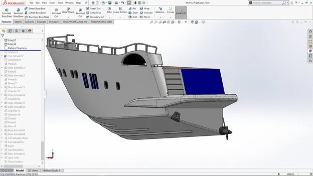
Fig 12: Model before linear pattern is applied.
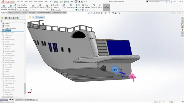
Fig. 13: Model after linear pattern is applied.
Mirror:
Mirror feature is used to mirror/copy the object, features in our model. When the feature is applied the property manager window will pop-up asking you the axis or plane in which you want your feature or object to get mirrored or copied. You can also select multiple features.
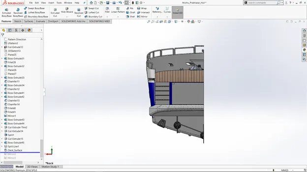
Fig. 14: Model after Mirror feature is applied.
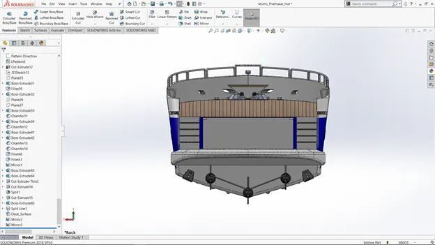
Fig. 15: Model after Mirror feature is applied.
Reference Geometry:
It is used to define a sketch or feature in an appropriate plane or axis. It is also used create a plane of our desired requirement to create a sketch on that plane and then get our model in desired position.
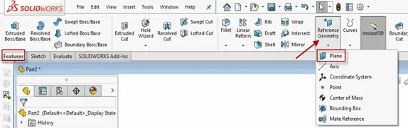
Fig. 16: Reference Geometry
Knit:
Knit is a feature which is used to bind/combine two or more faces and surfaces into a single body. It creates a closed body by filling or closing the gaps in between the edges.
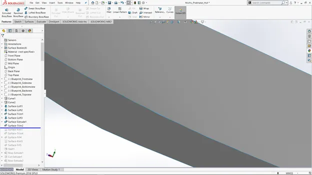
Fig. 17: Model before applying the Knit feature.
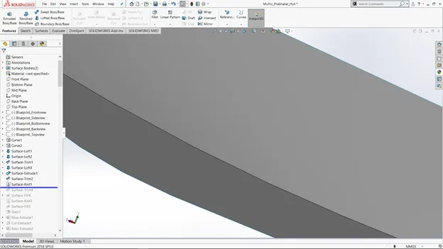
Fig. 18: Model after applying the Knit feature.
Mates:
Mates is the feature which you can see and use during the assembly of our parts into complete model. It creates a geometric relationship between two parts. When we apply mate, it defines linear or rotational motion to the parts to get it fixed at the right position with the other part. There are many mates which we can apply to the models, they are:
Coincident mate: coincident mate allows us to make two planes into coplanar. When we apply this mate, the part cannot be removed separate from the plane.
Tangent mate: Tangent mate is used to place the part and the plane in a tangent relation.
Concentric mate: Concentric mate is used to make the circular faces to be concentric and allow them to move along the axis.
Angular mate: Angular mate is allowed to make the part to be fixed at a certain angle with the flat surface.
Parts and its Design Procedure:
- Hull:
Hull is the main component of the Yacht. Hull, unlike chopper is designed using lot of surface feature rather than boss/base feature. Features used to create the Hull model are:
- Sketch
- Projected curve.
- Extruded Surface.
- Trim Surface.
- Lofted Surface.
- Swept boss/base.
- Extruded boss/base.
- Extruded cut
- Fillet
- Chamfer
- Mirror
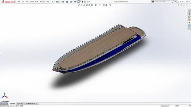
Fig. 19: Hull.
- Propeller:
Propeller, the important part of a hull is created by sketching it using appropriate features. Features that are used in modelling the propeller are:
- Sketch.
- Revolved surface.
- Lofted surface.
- Fillet.
- Chamfer.
- Extruded cut.
- Circular pattern.
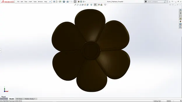
Fig. 20: Propeller.
- Radar:
Radar is an important instrument/device used in ships, yachts for detecting obstacles in the sea for a safer sail. The features used to create this model are:
- Sketch.
- Extruded boss/base.
- Extruded Cut.
- Fillet.
- Mirror.
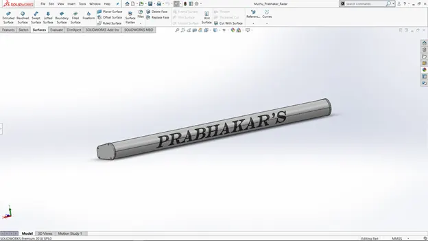
Fig. 21: Radar.
- Garage Door:
Garage Door is fixed at the rear side of the yacht. Garage in the yacht is used to load goods. It is created using drawing sketches and applying many features. Finally, appearance was added to the part based on our requirement. The features used to create the entire model are:
- Sketch.
- Extruded cut.
- Shell.
- Fillet.
- Mirror.
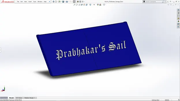 Fig. 22: Garage Door.
- Front Seat:
Front Seat is created according to the blueprints. Fillets are added to the edges. And finally, appearances are added. Features used to create the fender are:
- Sketch.
- Extruded surface.
- Swept Surface.
- Trim surface.
- Fill surface.
- Knit surface.
- Lofted surface.
- Extruded surface.
- Chamfer.
- Revolve.
- Fillet.
- Mirror.
- Dome.
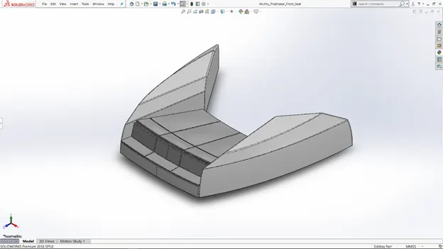
Fig. 23: Front Seat
- Rear Seat:
Rear Seat also follows the same procedure as the Front Seat but contains a lot of features involved. After the is created appearance is given to the Rear Seat.
Features used to create the Rear Seat are:
- Sketch.
- Swept surface.
- Offset surface.
- Trim surface.
- Ruled surface.
- Extend surface.
- Extruded cut.
- Extruded boss/base.
- Swept boss/base.
- Fillet.
- Mirror.
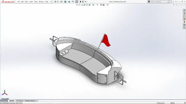
Fig. 24: Rear Seat
- Middle seat:
Middle seat is created according to the blueprint. The features that are used to create the front fork are:
- Sketch.
- Extruded boss/base.
- Extruded cut.
- Fillet.
- Chamfer.
- Mirror.
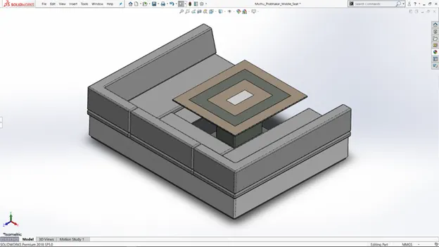
Fig. 25: Middle seat.
- Superstructure:
Superstructure is the huge space in yacht, which acts as the cabin. It is made by creating the half part of it by using lot of surface features. Then the other part is mirrored using mirror feature. Then the two parts are made into single part by using the knit feature.
Features used to create the superstructure are:
- Sketch
- Extruded surface
- Swept surface
- Trim surface
- Extended surface
- Lofted surface
- Fill surface
- Ruled surface
- Fillet
- Mirror
- Knit surface
- Extruded boss/base
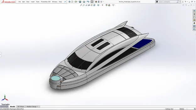
Fig. 26: Superstructure.
- Radarmast:
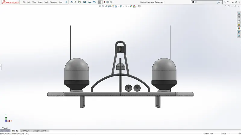
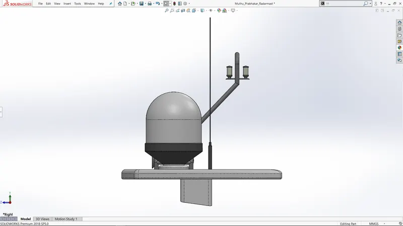
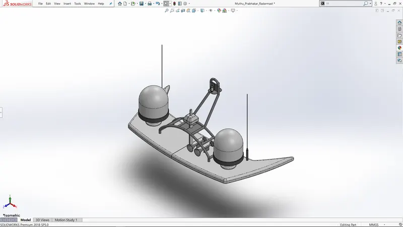
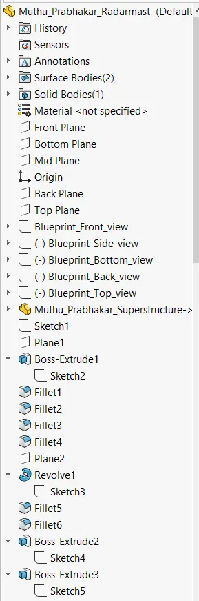
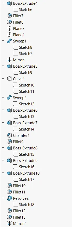
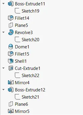
Radarmast is on the reference surface taken form the superstructure. It is created on one side and mirrored. Features used in creating the oil tank are:
- Sketch.
- Extruded boss/base.
- Revolved surface.
- Extruded cut.
- Shell.
- Dome.
- Fillet.
- Chamfer.
- Mirror.
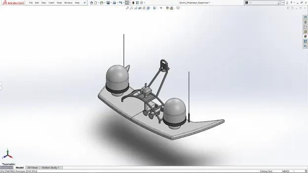
Fig. 27: Radarmast.
Assembly of the Chopper:
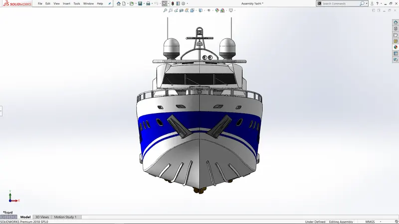
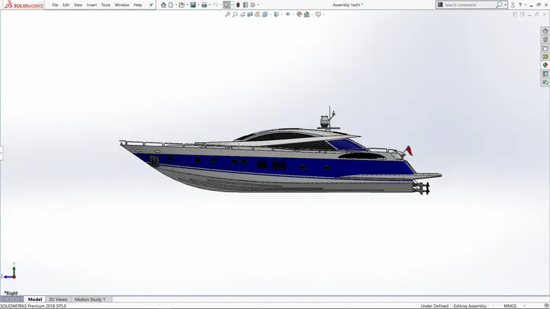
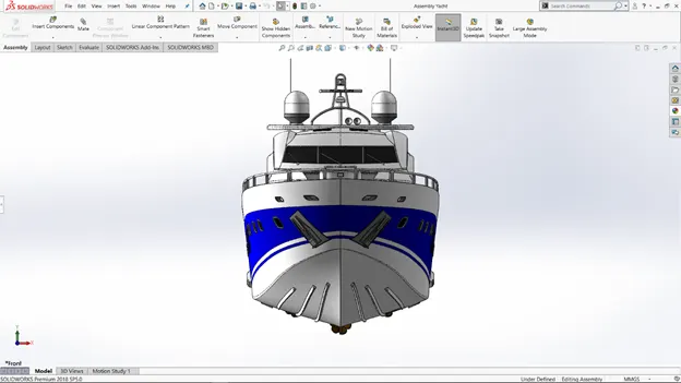
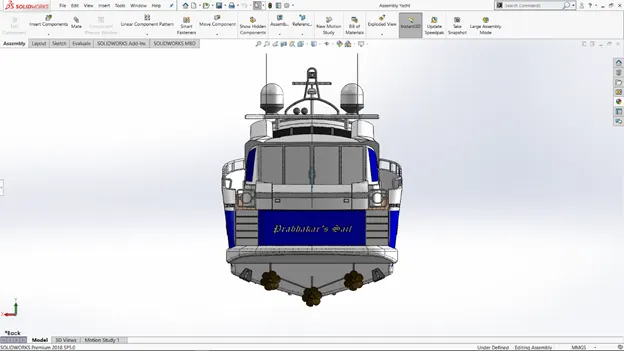
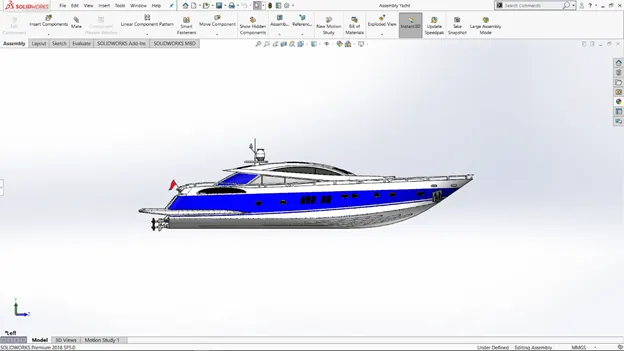
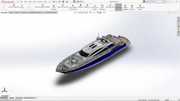
All the parts that are modelled using Solidworks, has been imported to assembly window in solidworks to assemble them. In assembly, mate is the feature which is most commonly used to locate and relate the parts with one another.
Hull is acts as the main component which is inserted and then fixed, at first. The other components are brought in and then inserted one by one by using planes for reference and giving them proper definition using mate feature once the parts are placed. Some parts are modified during assembly to make it perfect according to requirement.
Decals:
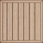
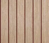
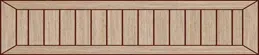
A decal consists of a picture, image, pattern, or design that’s printed on a metal body. We have added decals on Hull surface, Jacuzzi stairs. It gives nice appearance to the yacht.
Rendering:
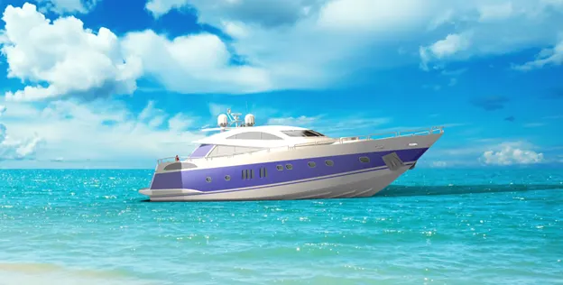
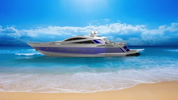
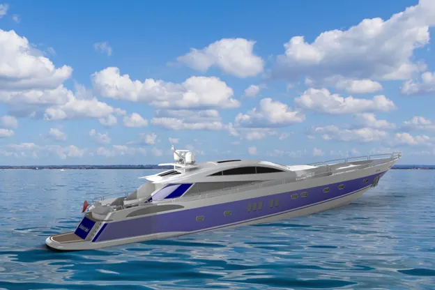
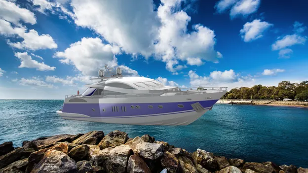
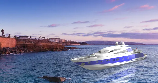
Rendering is the term used to refer the artistic drawing, how it will look in the future or how the output will look like. Rendering of our Sunseeker Predator Yacht model is done in the SOLIDWORK Visualize software. By using PHOTOVIEW 360, we can add various camera views to the model, we can set various angles, direction, and can set appropriate distance to get the perfect camera view. In SOLIDWORK Visualize software, we can change the color of chopper parts, background, brightness, rotation and various settings of predator yacht. By adjusting the resolution and setting number of passes, we get more detail visuals of the yacht. Rendering is done to check how our predator yacht model will look in the environment.
Conclusion:
Thus, the modeling of Sunseeker Predator Yacht is completed using Solidworks and the rendering of the same is done in Solidworks Visualize.