Week 8 - Challenge 2 - Base Bracket Design
AIM : To Create the Base Bracket Plastic component through the given Class-A surface. To begin with, the tooling axis for the given Class-A Surface should be created meeting the requirements of the draft angle and at the end perform the Draft analysis on the model.
PROCESS :
Commands or features used.
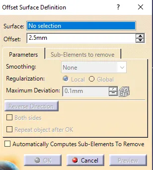
Offset is used to create a copy of parental surface at a particular distance.
The surface needs to be selected and distance from the parental surface should be mentioned.
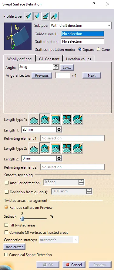
Sweep is executed to generate a surface. There are various methods in sweep. The necessary method is choosen to perform operations further.
Tooling axis and guide have to be selected so that along the selected boundary (i.e. guide) a surface can be generated.
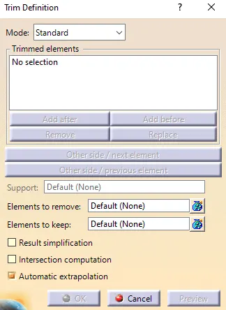
Trim is used to remove unwanted surfaces. We ensure that the surfaces which have to be trimmed should intersect with each other.
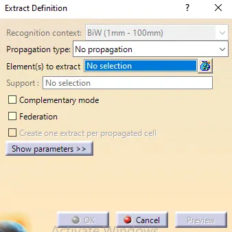
Extract is used to take out a surface and separate it from parent.
This helps us to work particularly on each surfaces.
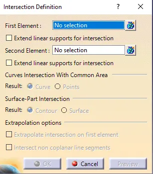
Intersection makes two surfaces to intersect. Elemental surfaces need to be selected.
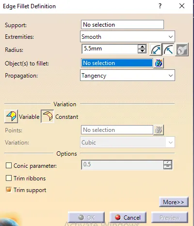
As fillet is rounding of exterior or interior corners in part desgin, this command helps us to execute it.
Commonly used fillet here is edge fillet. The edges and radius at which fillet has to be executed have to be given.
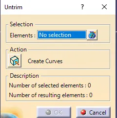
Untrim is reverse of trim. Non trimmed surfaces are made to come back again. Just selecting the surface does this operation.
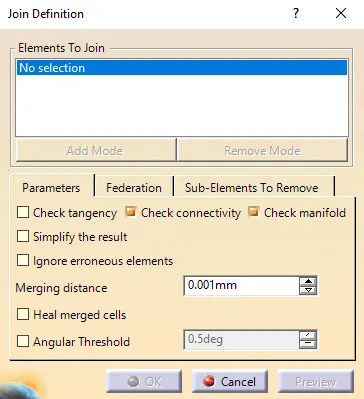
Join attaches unjoined elements or surfaces together.
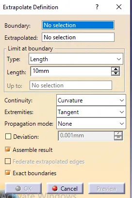
Extrapolate increases the dimensions of elements or surfaces. This helps us to trim off elements as they bound to intersect with each other in this operation.
MODEL :
CLASS A SURFACE is shown below. They are nothing but external or internal surfaces which are visible and have curvature continuity.
Tooling axis refers to the direction at which core and cavity opens. It has to be perpendicular to the part.
Tooling axis is created in the below image.
Intersection is made and bisecting is done by use of drawing two lines on either sides.
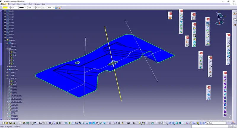
CLASS B
(The are mostly not visible. They are replica of class B but have tangent continuity.)
The flat surfaces in class A is extracted ,untrimmed and extrapolated.
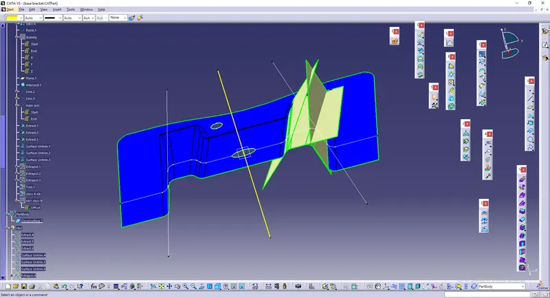
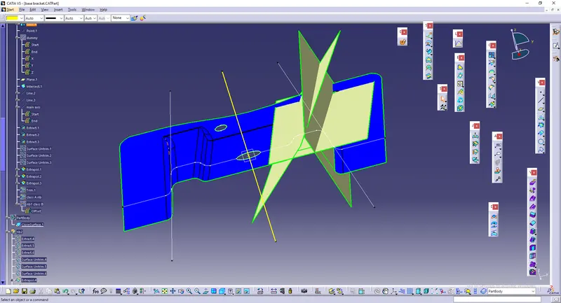
After the above process, Offset of 2.5mm is made. The unwanted surfaces are removed using trim.
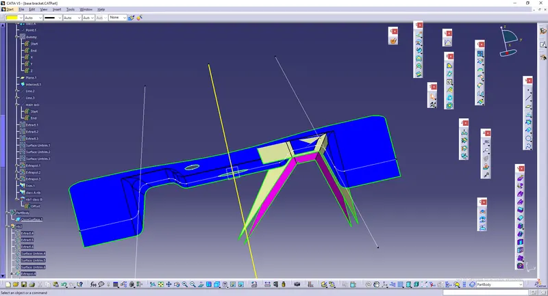
As the fillet regions may complicate the process,only flat surfaces are extracted and work is done.
By measuring Class A, value of fillets are given to class B.
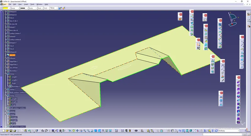
CLASS C
This is the surface that joins class A&B
Class C is made using sweep. The draft angle is set as 3 degree.
Tooling axis is used as tooling direction.
The intersected element is extracted and it is used as guides.
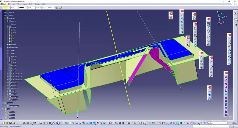
Multi sectioning is done to join surfaces together.
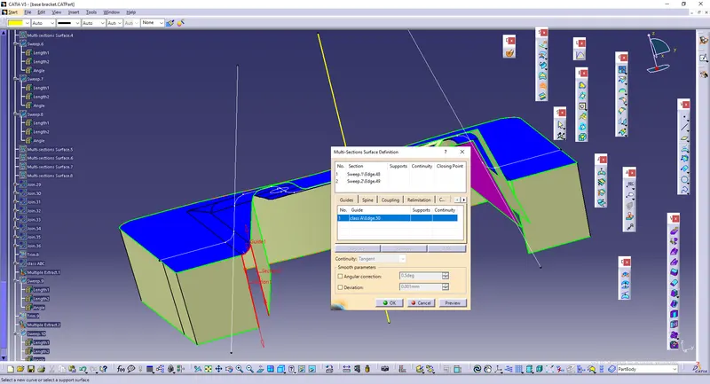
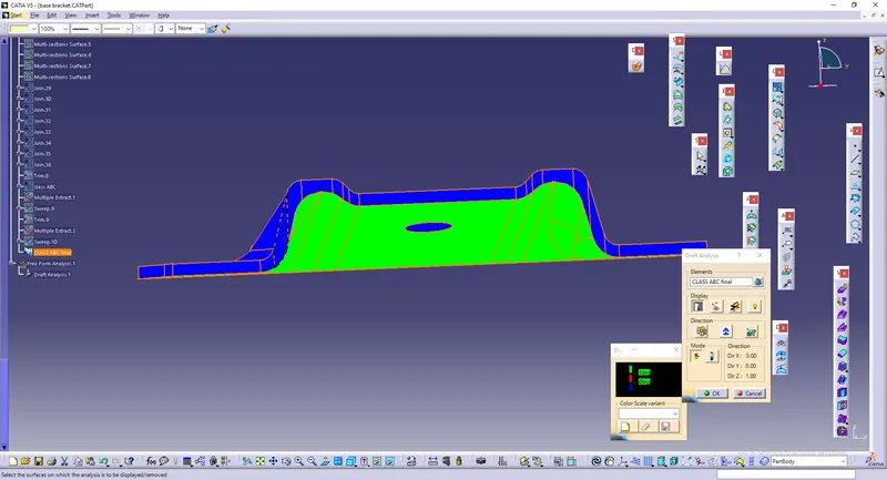
Over all Class ABC.
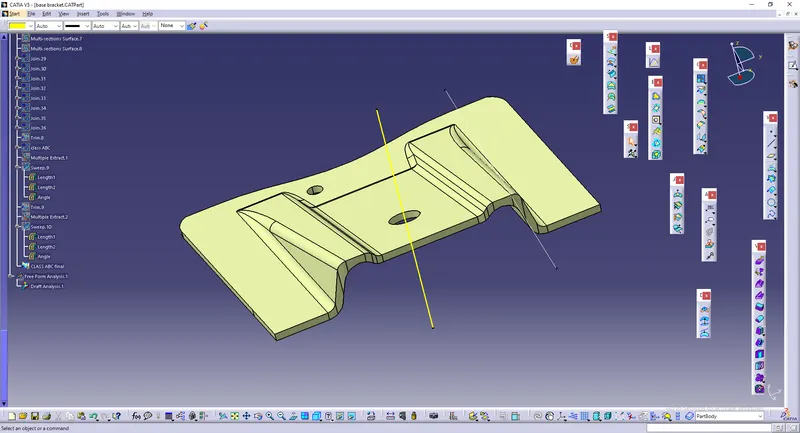
The model is then converted into a part.
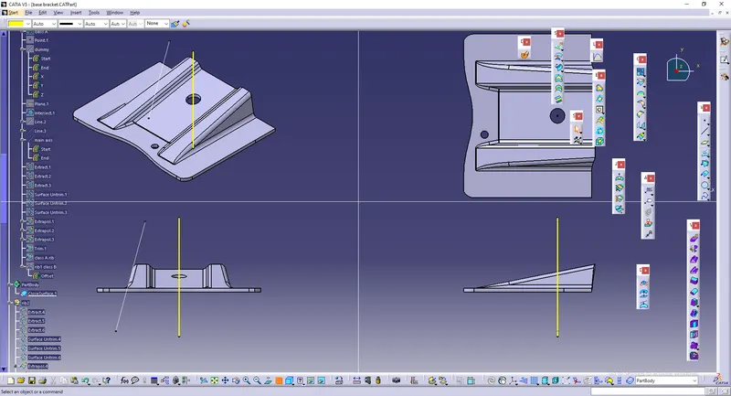
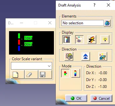
Draft analysis is done to measure angles.
As we could see ,the generated class B and C are cleared in draft analysis.