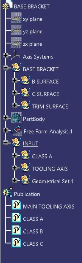
Week 8 - Challenge 2 - Base Bracket Design
DRAFT ANALYSIS ON BASE MOUNT BRACKET
The report summarises the draft analysis made on the base bracket. Further elaborating the stages of development of the Class-B and Class-C surfaces from the given Class-A surface.
The tooling axis would define the path/direction in which the part would be molded and cleared during a molding operation.
The draft analysis is made to check the molding possibility of the component. Initially, the given class-A surface is checked for continuity using the boundary command.
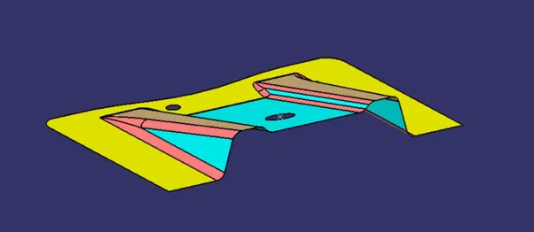
Given class-A surface:
Once the continuity check is done, a dummy tooling axis is created as per feasibility.
the intersect curve is created with class A in the YZ plane.
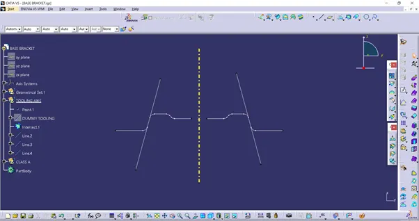
The line is developed which the surfaces tend to be problematic.
Then the bisecting line is formed, which is the main tooling axis.
The minimum draft relies on different components. The draft of 3 degrees is the minimum industry standard.
Now on identifying the main tooling axis.
- The feature draft analysis window is opened.
- The compass is brought and aligned to the mail tooling axis.
- In the indexing window, the minimum draft is given as 3 degrees.
- Now click on any region of the part.
The output is as given below,
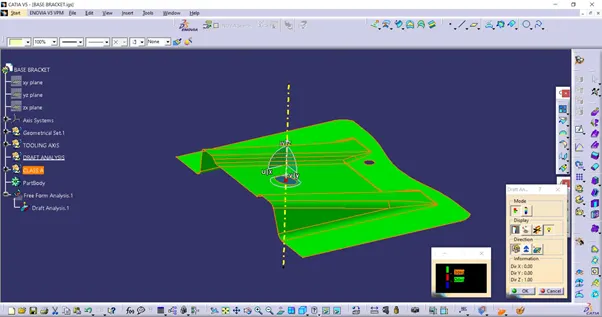
The green output shows that all the surfaces are more than 3 degree
Hence, the part would clear the tooling.
The class B and Class C surfaces are generated from the given Class-A surface.
Class A- It is the aesthetic surface of the component.
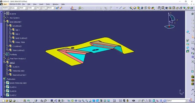
Class B- It is the surface that contains engineering features
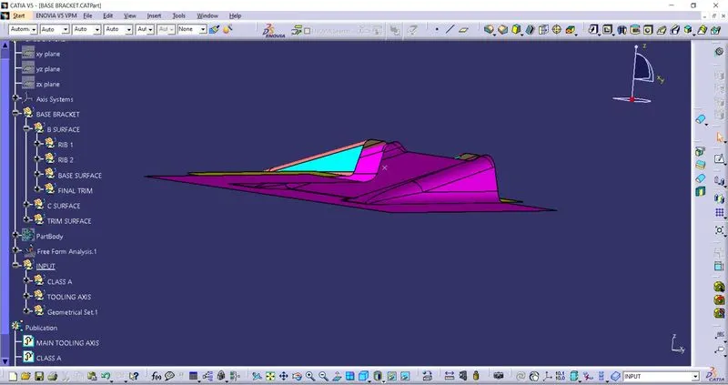
Class C- The surface which joins Class A with the Class B surface.
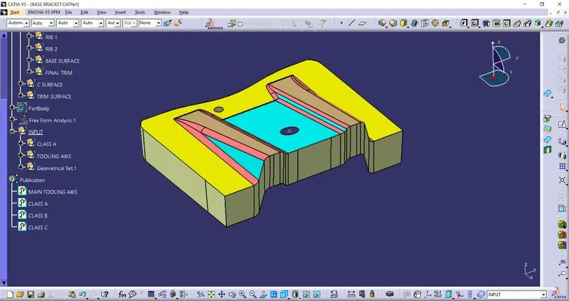
HOLLOW BODY:
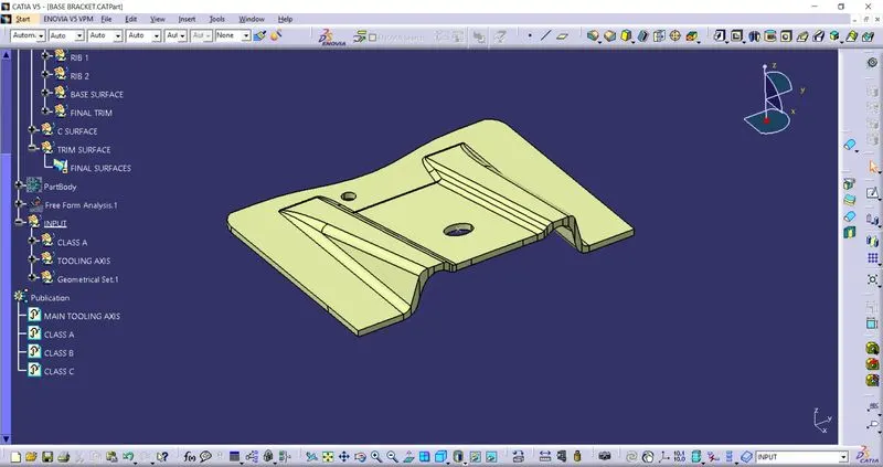
SOLID BODY:
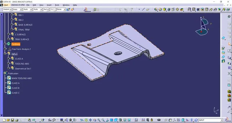
THE TREE STRUCTURE: