Week 8 - Challenge 1 - Draft Analysis on a Fan Cover
FAN COVER
Class A surface:

Tooling Axis:
To create Tooling axis, An axis system is created at the center point.
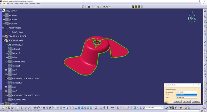
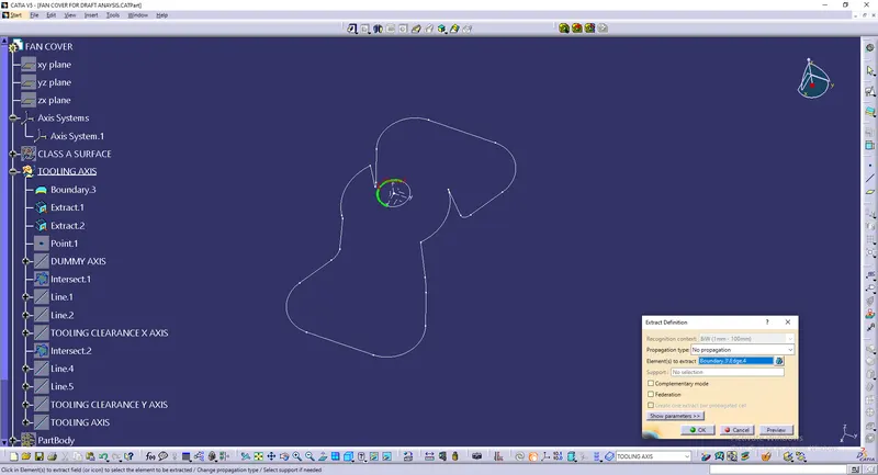
Then, the boundary for the Class A surface is extracted using BOUNDARY command.
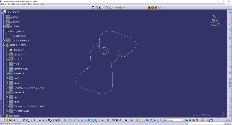
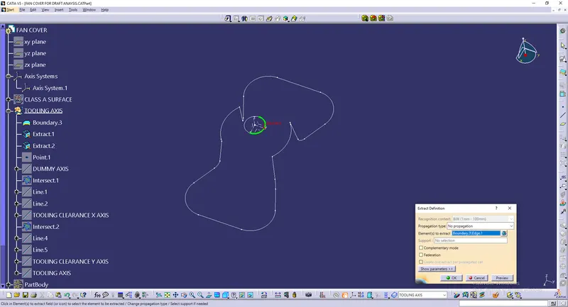
The hole at the center is extracted seperately.
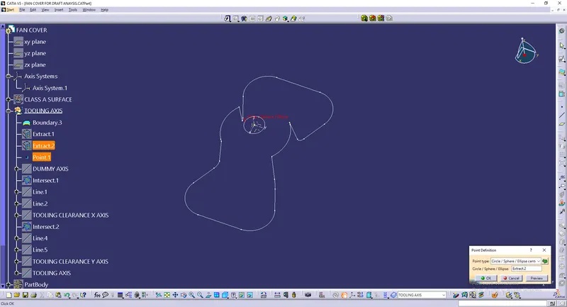
A point is created at the center.
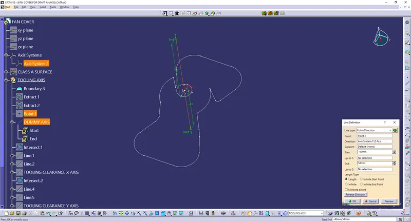
A dummy axis is drawn with reference to the center point.
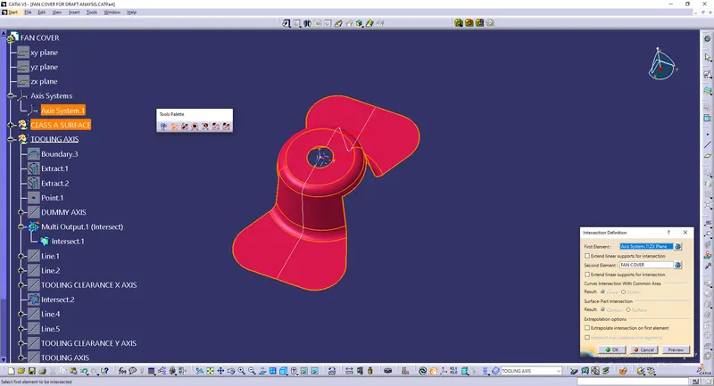
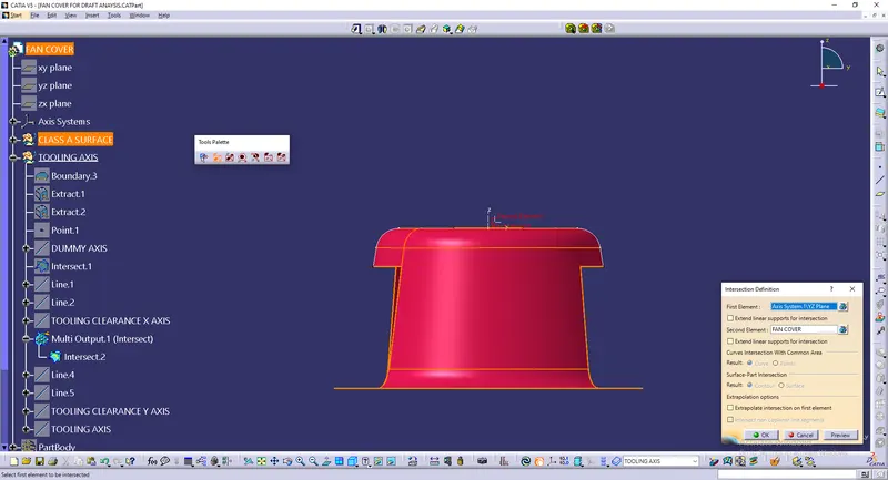
Then have taken the intersecion of the whole Class A surface of FAN COVER with respect to zx plane. And the center line indicates the intersecting section of the Surface on ZX plane.
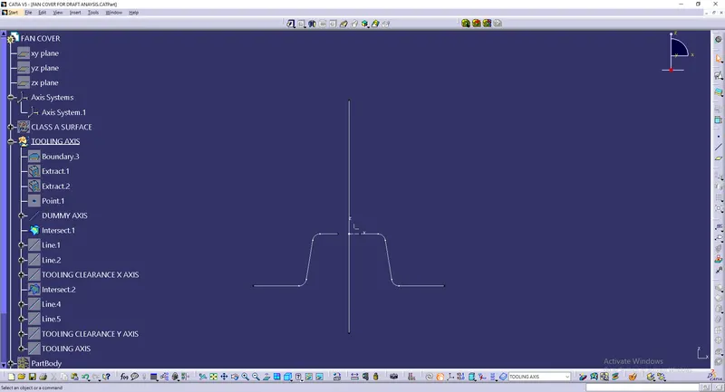
All the intersected lines should clear the draft anlysis with respect to the dummy tooling axis. And the perpendicular lines will surely clear but only the parallel lines should be noted.
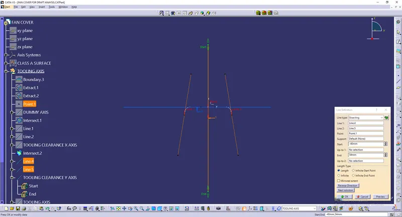
A line is drawn with the reference with the points on the intersecting lines which are parallel to the dummy axis.
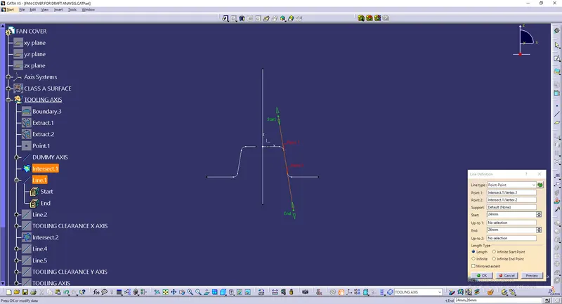
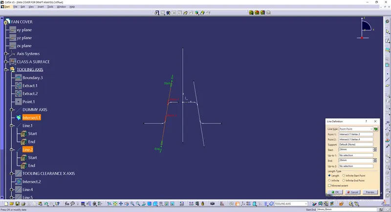
A bisecting line is drawn for the lines drawn above with reference to the intersecting lines. And this line is know as the TOOLING CLEARANCE X AXIS.
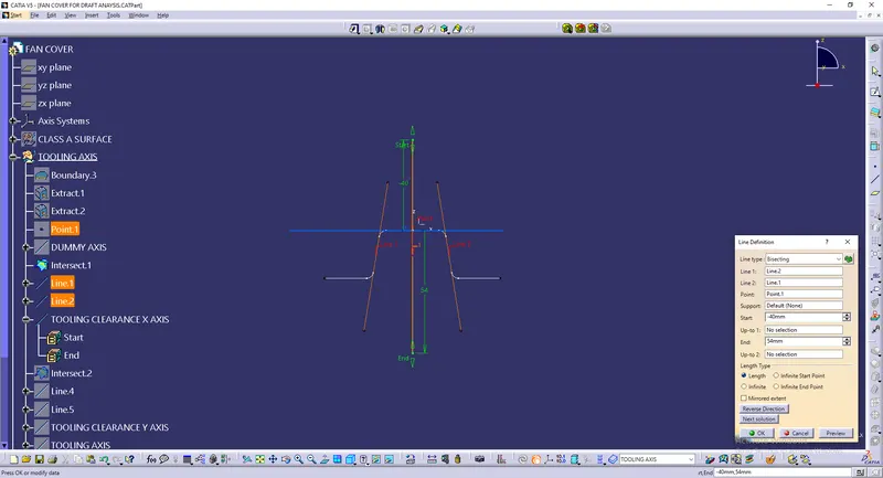
Now another side of the Class A surface is taken intersection on YZ axis. And got,
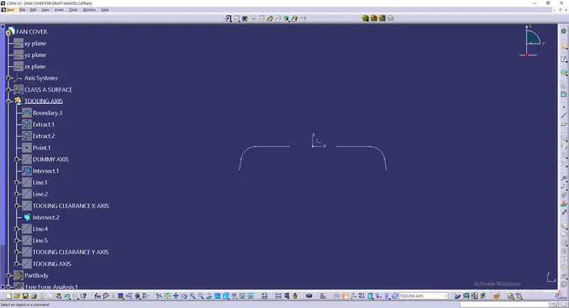
The same method is followed here too, a line is drawn on the parralel intersecting lines for the dummy axis.
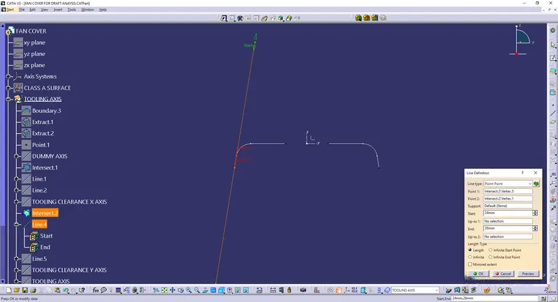
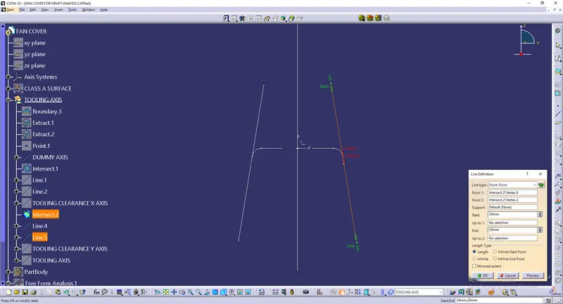
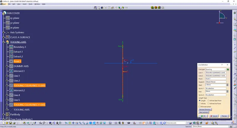
A bisecting line is drawn for the lines drawn above with reference to the intersecting lines. And this line is know as the TOOLING CLEARANCE Y AXIS.
For both the Tooling Clearance Axes another bisecting axis is taken and this line is the TOOLING AXIS.
DRAFT ANALYSIS
Here in this Draft analysis, Criteria will be given on which the draft of the surface can be analysed with respect to the Tooling axis.
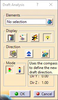
The axis is drag to the tooling axis with which the draft analysis is to be done.
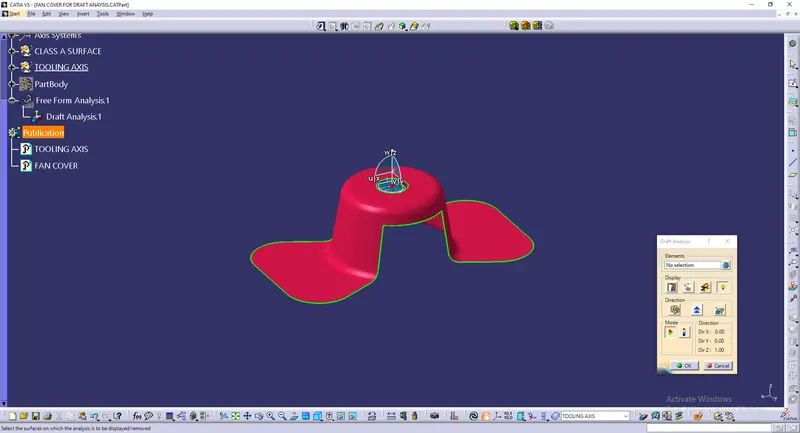
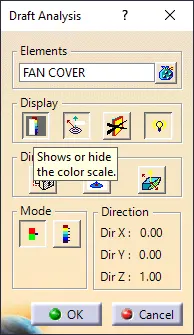
Here in the Draft anlysis, Under Display, Choose the option "Shows or Hide the color scale". To differentite the surface based on the draft criteria entered.
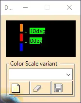
Green for the surface failing to achieve 10deg.
Red for the surfaces failing to achieve 0deg is assigned.
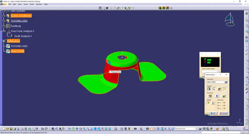
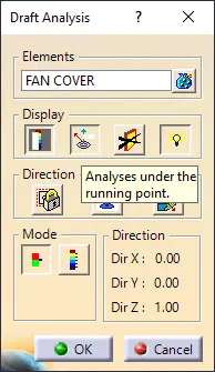
In the Draft Analysis, With the help of "Analyses under the running point" we can measure the deg of the surfaces like tha above image attached.
Now, according to our criteria, deg 3 is set.
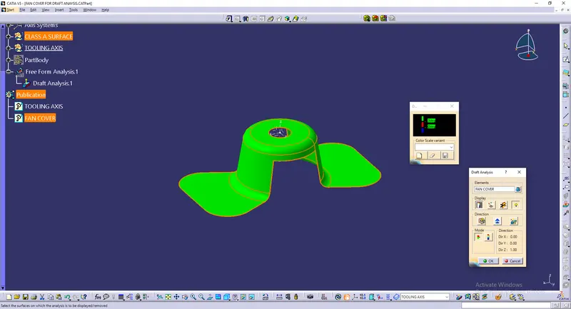
Front view
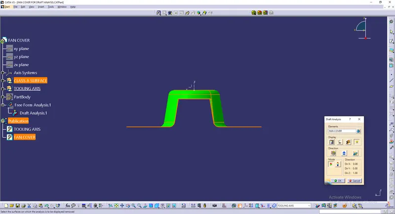
Side view
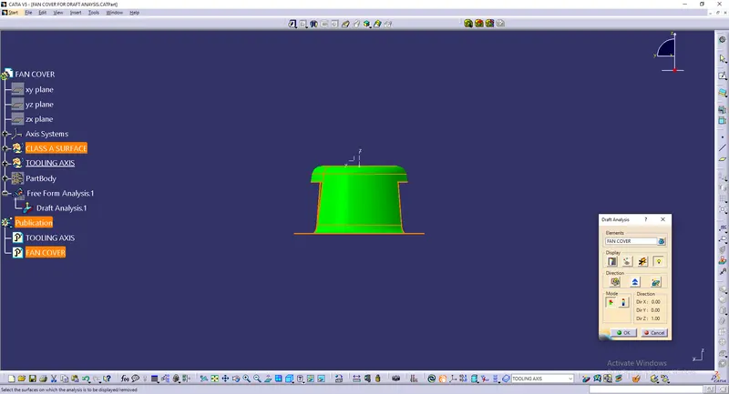
Top view
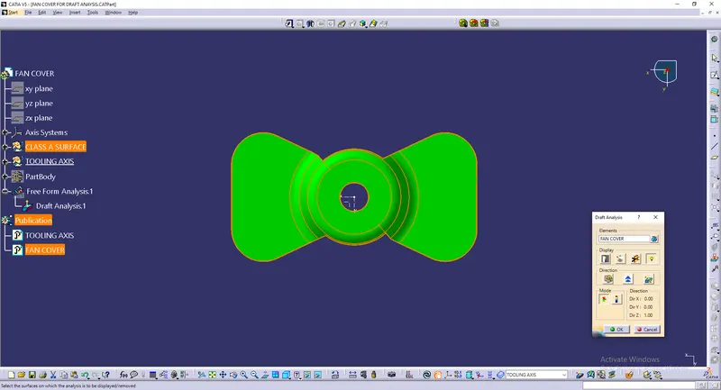
PUBLICATION
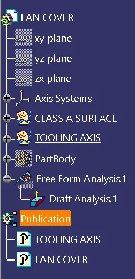
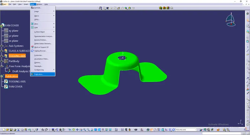
Publication is done by defining the Geometrical set or the Part body which is to be published and then move to the TOOLS in the top menu and select the last option PUBLICATION.

TREE STRUCTURE