Door Arm Rest Week 8 Challenge
DESIGN OF CLASS B AND CLASS C SURFACE FOR DOOR ARM REST
Aim
The main objective of this project is to create Class B and Class C surface for the door arm rest using catia work bench following industry standards.
Instructions
The below steps represent the phases in which the door arm rest console was designed
- Bringing the aesthetic Class A surface of the Door arm rest.
- Determining main tooling axis for the Door arm rest.
- Determining slider tooling axis for the undercut.
- Performing Draft analysis for both the tooling axis.
- Designing of Class B surface.
- Designing of Class C surface.
Design Procedure
- CLASS A SURFACE
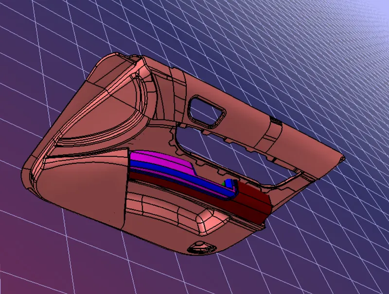
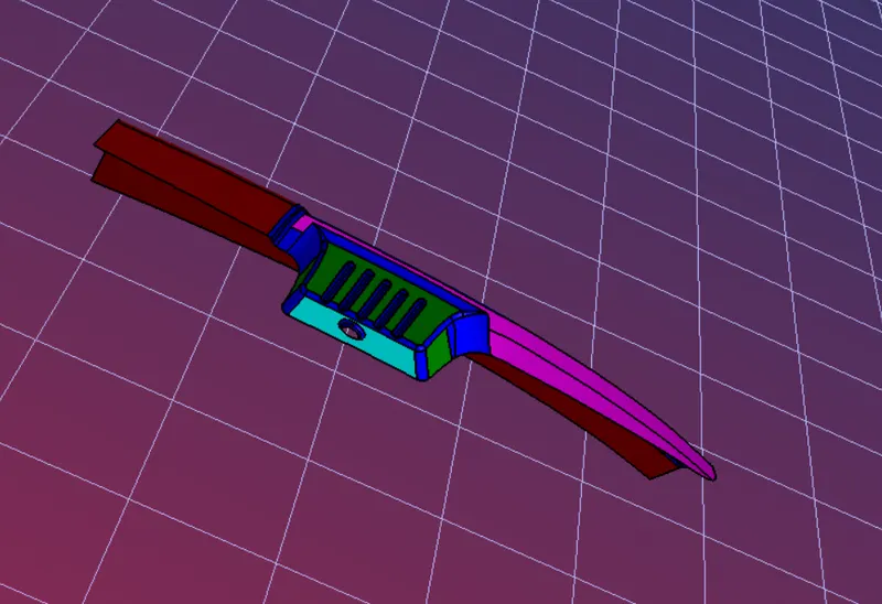
The first step in designing the product is to bring the class A surface provided by the OEM to the Catia work bench. Below figure represents the class A surface.
- DETERMINATION OF TOOLING AXIS
In the process of designing plastic component, tooling axis plays an important character for determining the position of line through which the core and cavity can be opened safely. The tooling axis is also important for the reference of direction of draft angle for the safe removal of the component from the die.
For the given component the first tooling axis is created by following method
Intersection along X direction with the door arm rest is generated and then two lines are created along two edges, the mean line is created between the two lines to get desired axis as shown below
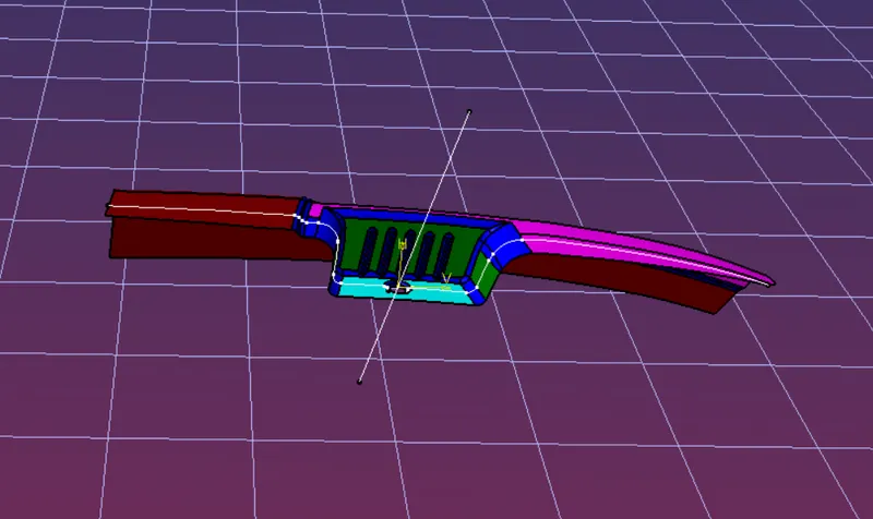
Now the intersection is done along Y direction.
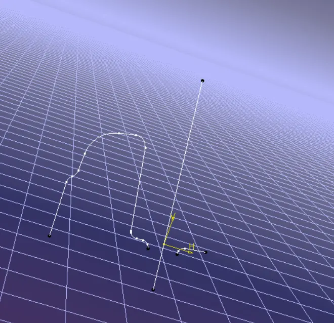
The main tooling axis is created by generating the mean line between the axis along X and Y direction made earlier.
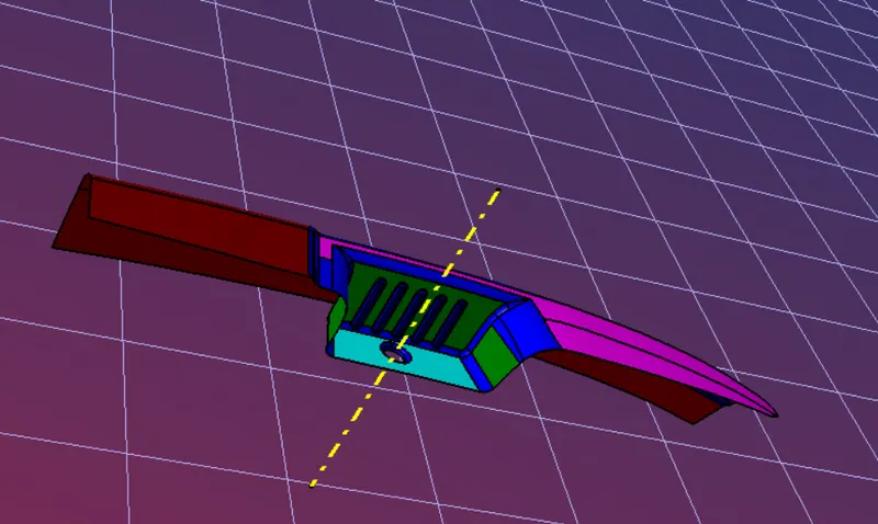
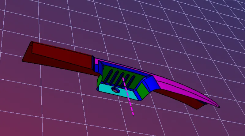
As the component is having an undercut, another slider axis needs to be created for the safe creation of the shape of the component.
The slider tooling axis is shown below
- Draft Analysis
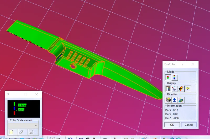
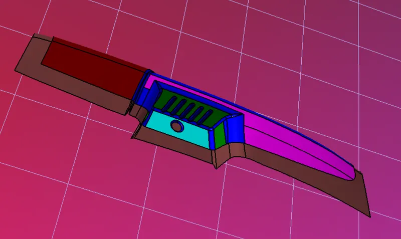
The draft analysis plays an important part in determining whether the component we created and drafted can be easily removed from the mould.
Draft Analysis along main tooling axis
- CLASS B SUFACE
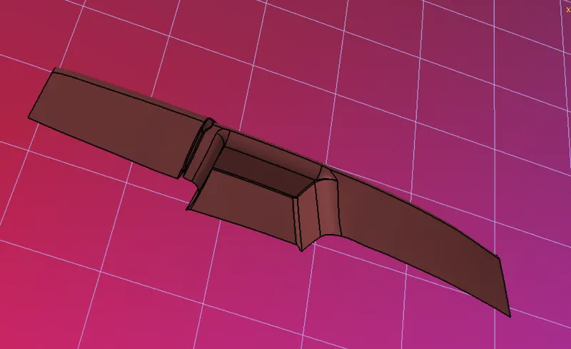
The class B surface is created at an offset distance of 2.5 mm below the class A surface.
Class B surface is the surface on which all the supports are attached for giving the component firmness with the body to be attached and perform various other engineering aspects for proper creation of component.
- Class C surface
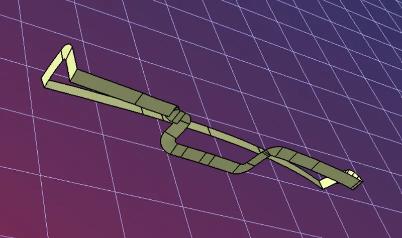
The class C surface is the connecting surface between the class A and class B surface.
This surface is created with a 3 degree draft from the class A surface along the main tooling axis direction for the safe removal of the component from the mould after performing injection moulding operation.
In order to create this surface, first step is to extract the boundary of the class A surface and then perform sweep operation using along draft direction option and provide an angle of 3 degrees for the swept surface to get the desired shape.
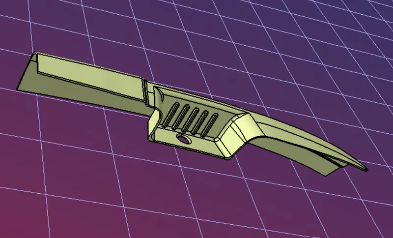
After creating all the three surfaces (i.e., class A, class B and class C surface's) all of them are joined together using the join and trim feature to make this into a closed surface.
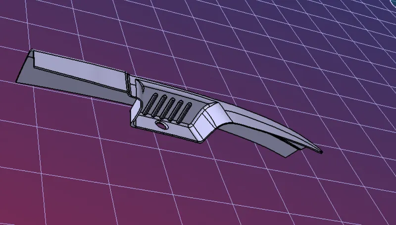
This closed surface is then converted into a closed body after ensuring that the surface is closed from all directions and then close surface feature is used to create the body from the surfaces.
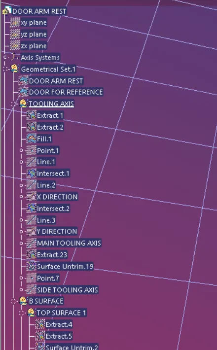
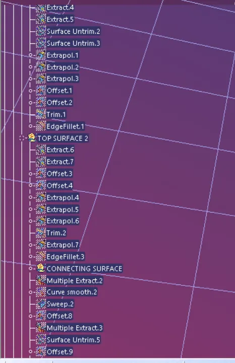
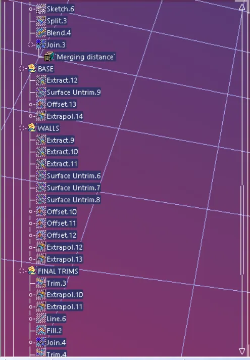
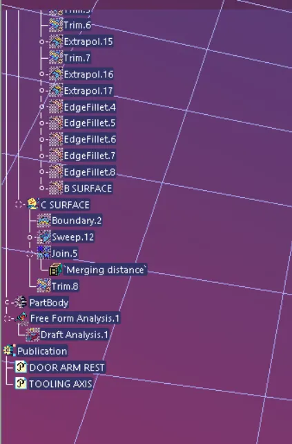
Detailed tree structure is shown below which represents all the operations that were performed in order to make the component.Proper names are given to the geometrical sets for proper identification and creation of the surfaces for better understanding of the component in the future as well. Certain operations are published for easy visibility of certain final operations.
Conclusion
- The class A, class B and class C surfaces were designed successfully according to industry standards for the manufacturing process through injection moulding.
- Tooling axis for the component was determined and the undercut was identified at the certain place, for this area to be manufactured in desired shape a slider would be required. The direction of the slider was determined using slider tooling axis.
- Draft analysis along both main tooling axis and slider direction was performed to analyse the safe removal of the component after performing moulding operation.