Week 8 - Challenge 1 - Draft Analysis on a Fan Cover
Draft Analysis on a Fan Cover
Introduction
No parts can be ejected from the tool if it is having a straight 90 degree profile from its base surface. A small draft angle is provided to each and every area of the component in order to get an easy removal of the component from the tool. Draft analysis technique is used to analyze whether our part model created in cad is manufacturable based on the draft condition applied. Here the part should get easily removed from the panel dies (in case of Sheet metal part) or Mold (in case of plastic). Here we are providing a direction in which components should eject inorder to get an easy removal of components from the tool. In other words it also lets us know whether the model is having a draft angle and how much is the draft angle from the tool direction.
Steps
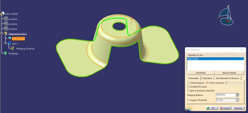
- First ensure the class-A surface is properlly and has no discontinuity on it. For this we can use boundary command or join command.
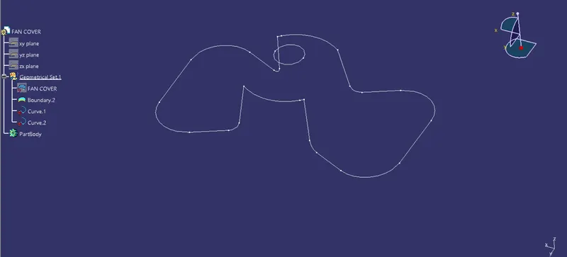
- Analyze the model manually or visually to see which direction is more suitable for tooling axis.
Here we are seeing the isometric view of the surface and can clearly see a hole on the top surface.
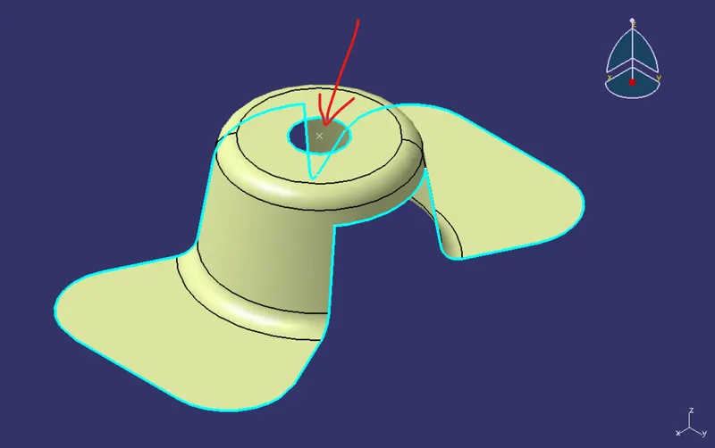
From X-direction, it will be difficult for tooling the hole.
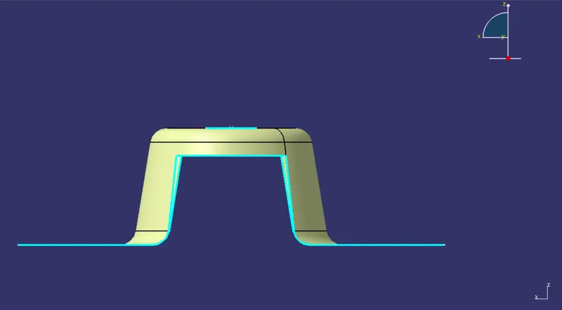
From Y-direction, it will be difficult for tooling the hole.
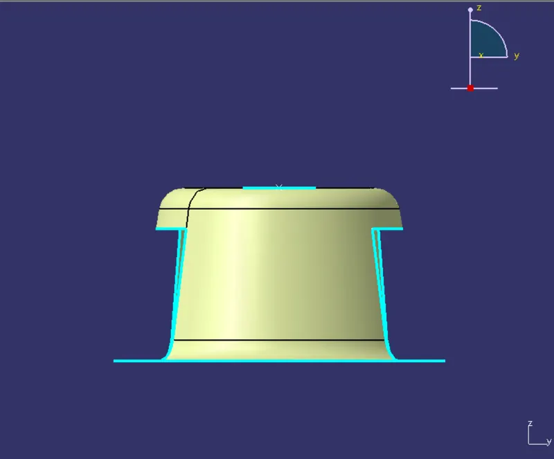
From the Z-direction the hole is visible so we choose this direction for tooling axis. Note that this is only a dummy axis
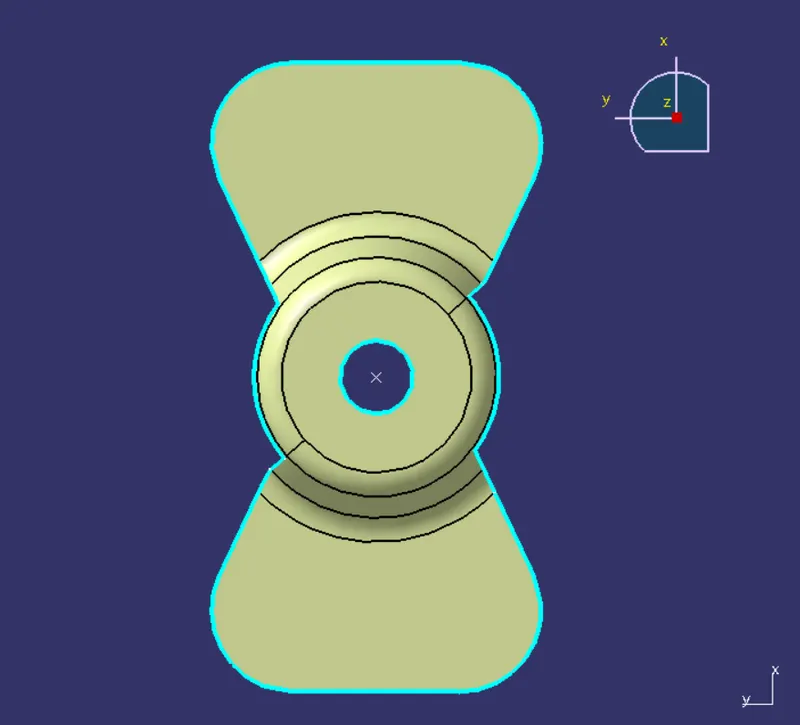
- Now we will use the bisecting method to make the real tooling axis.
Make an axis system and intersect the ZX-plane with the class-A surface.
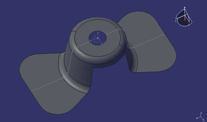
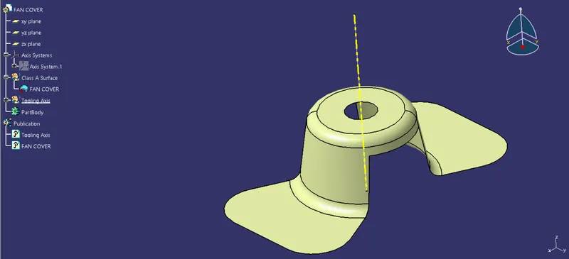
A dummy tooling axis is created at the centre point as shown in below figure.
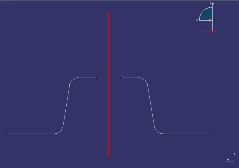
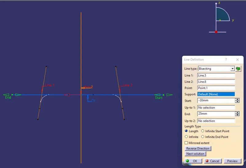
Add two lines using point to point relation lines at two ends as shown below.
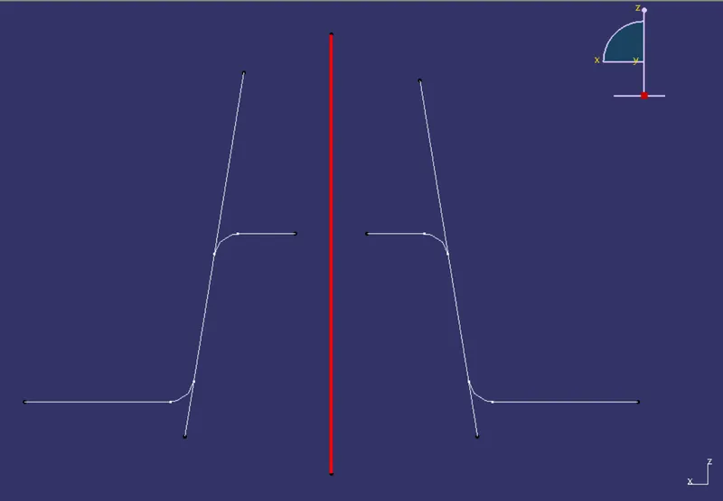
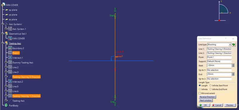
Add bisecting lines using the two lines created.
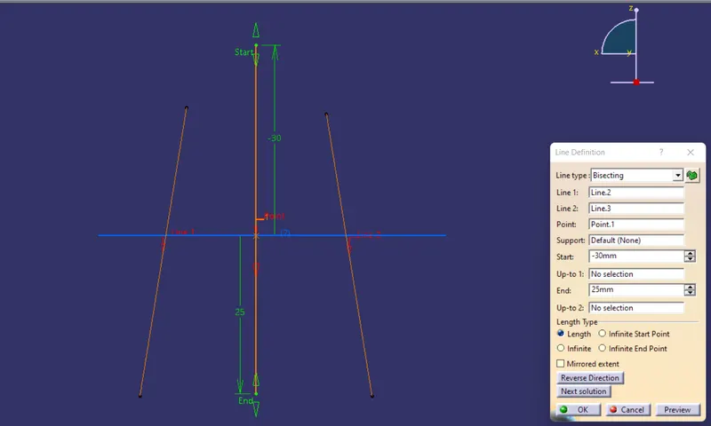
We get a centre point line at the centre of the model.
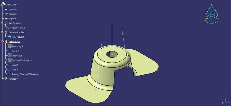
Similarly we use YZ-plane of the axis system with the class-A surface.
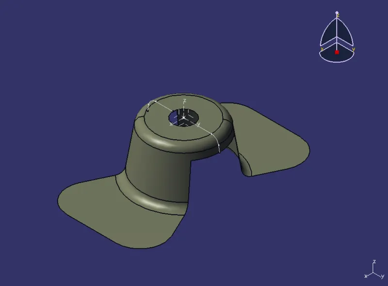
Publications: Used the publication option and publish the below
- Tooling Axis
- Class A surface
Draft Analysis
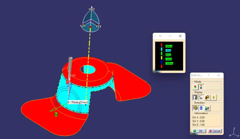
- Go to Insert>Analysis>Feature Draft Analysis.
- Click on the compass icon and align it with the tool axis and click on the surface, we will get our results.
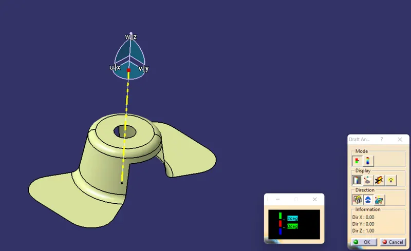
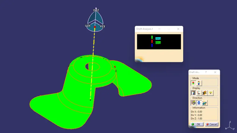
Draft at 2 degree.
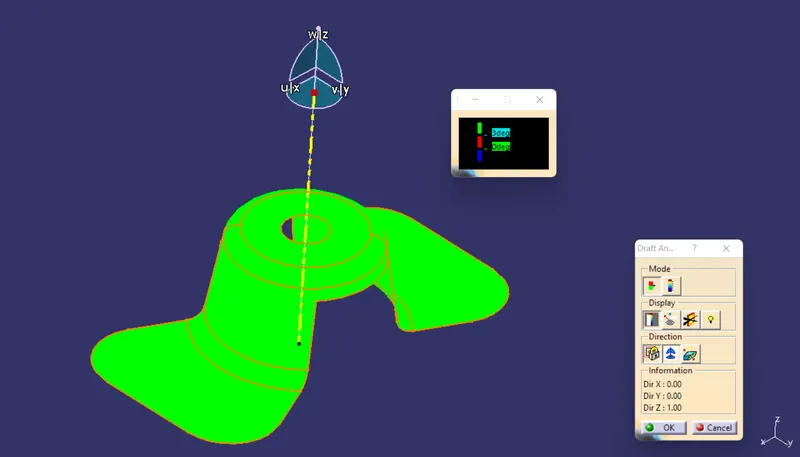
Draft at 3 degree.
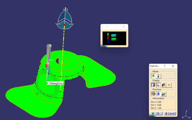
Analysing side surface draft angle.
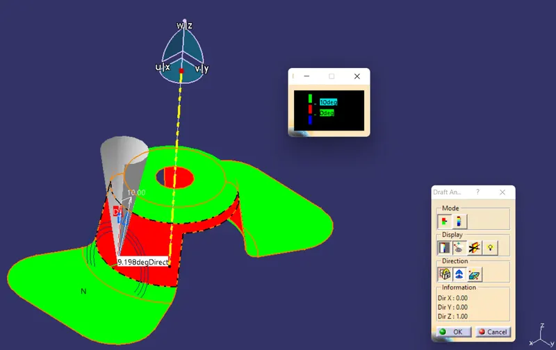
Draft at 10 degree.
Front View
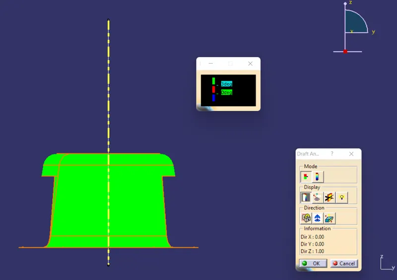
Side View
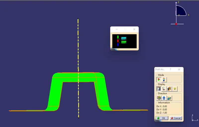
Top View
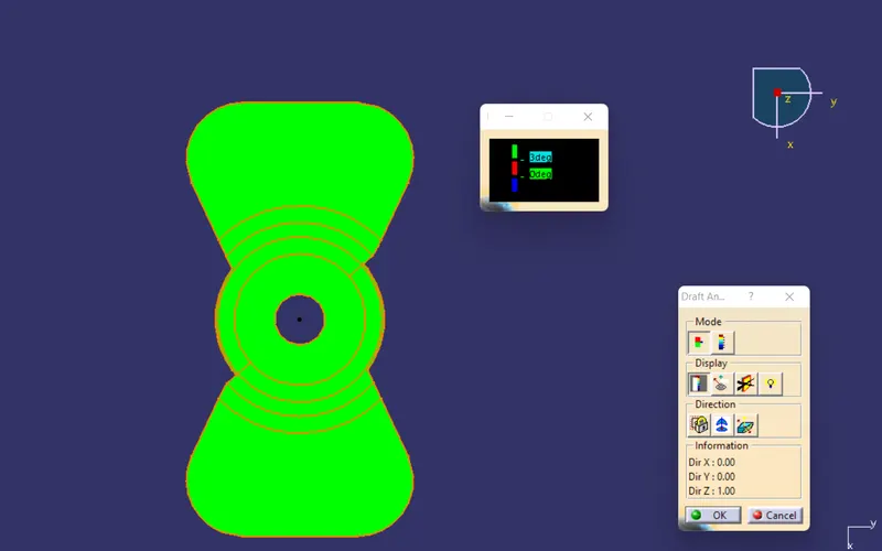
Isometric View