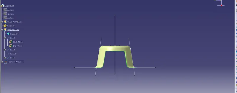
Week 8 - Challenge 1 - Draft Analysis on a Fan Cover
Draft:
Drafts are defined on molded parts to make them easier to remove from molds. There are two ways of determining the objects to draft: either by explicitly selecting the object or by selecting the neutral element, which makes the application detect the appropriate faces to use.
Draft Analysis:
It is a tool that allows the user to ‘see’ whether the part they are designing can be removed from the tool being used to make it. In the case of plastic injection molded parts it also allows the designer to see if there is enough draft on the part to ensure that it can be correctly grained.
The draft analysis button within CATIA V5 will helps you quickly gather the draft angle on multiple surfaces without the need for tedious manual measurements. Here is a quick rundown of how the icon works when you have a given die direction.
FAN COVER:
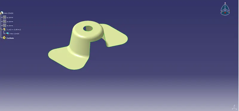
DRAFT ANALYSIS ON A FAN COVER:
STEP 1:
Intially creating a Point on a Fan Cover, point represents the position sketch
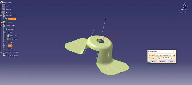
STEP 2:
Tooling Axis controls how you want the tool to orient itself whilst cutting a multi-axis toolpath. The default value is Vertical which is used for standard 3-axis
The next step is create a Tolling axis on Fan Cover, In this component z axis is taken as the tooling axis
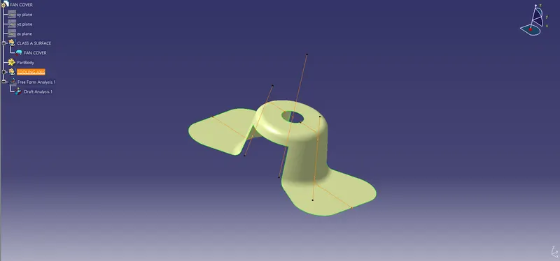
STEP 3:
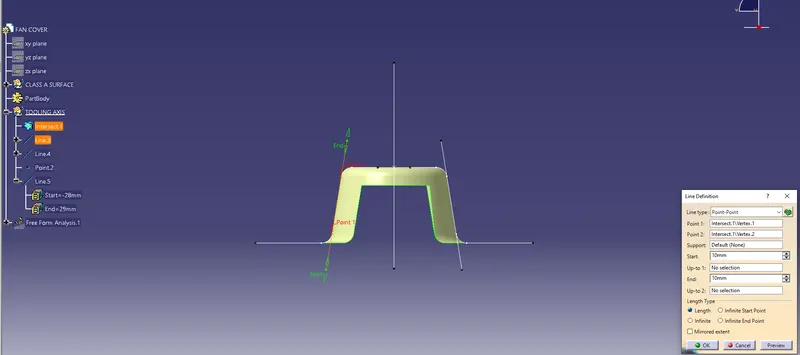
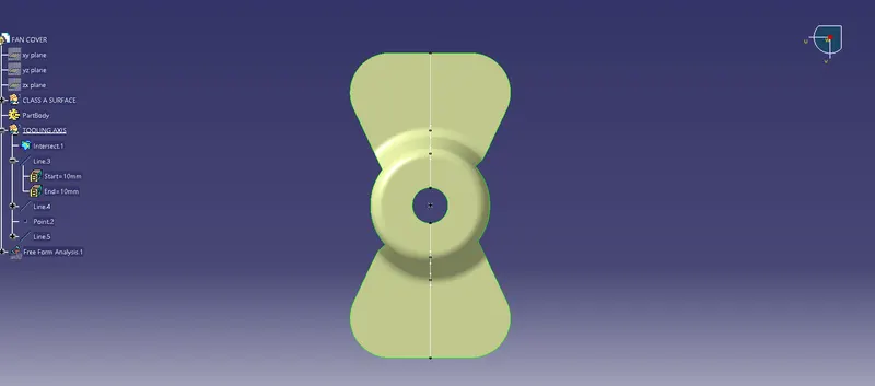
Creating a intersecting line, Line3
STEP 4:
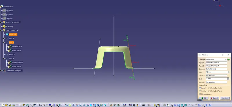
Creating a intersecting line, Line4
STEP 5:
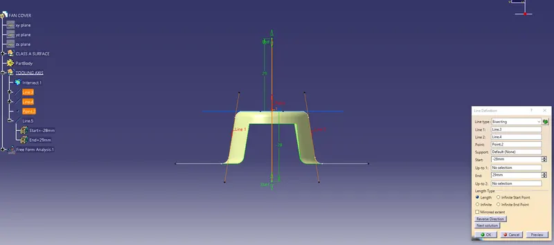
Finally Bisecting line , Line5
STEP 6:
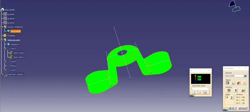
This is the Final step Draft Analysis
a) Fan Cover with lock cammand-:
b) Fan Cover with compass-:
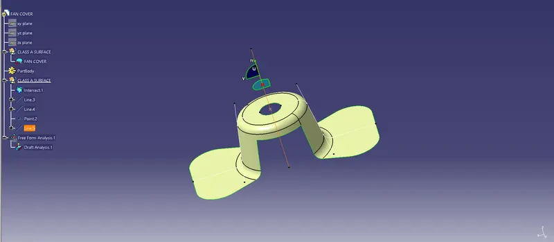
c) Fan Cover with Running point-:
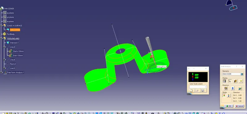
In this 3 colors represents are Green, Red, & Blue, what these 3 colours represents is given below
Green- more than 2 degree
Red- between 0 to 2 degree
blue- negative value
In this the running point is used to see the angle, i.e which is measure the angle
d) Fan Cover with Full Analysis Mode-:
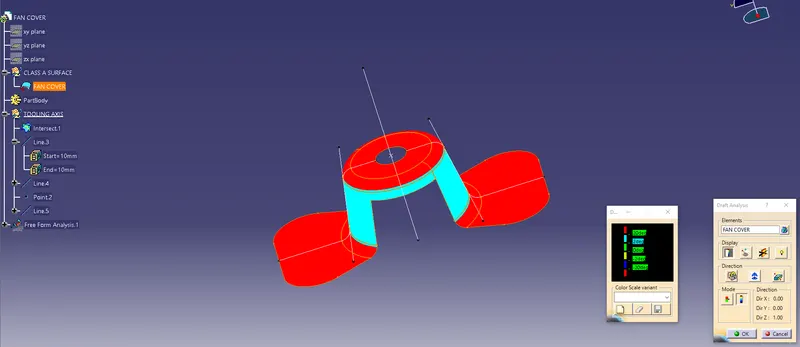
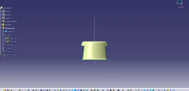
3Views of Fan Cover:
Front view:
Top view:
Side view: