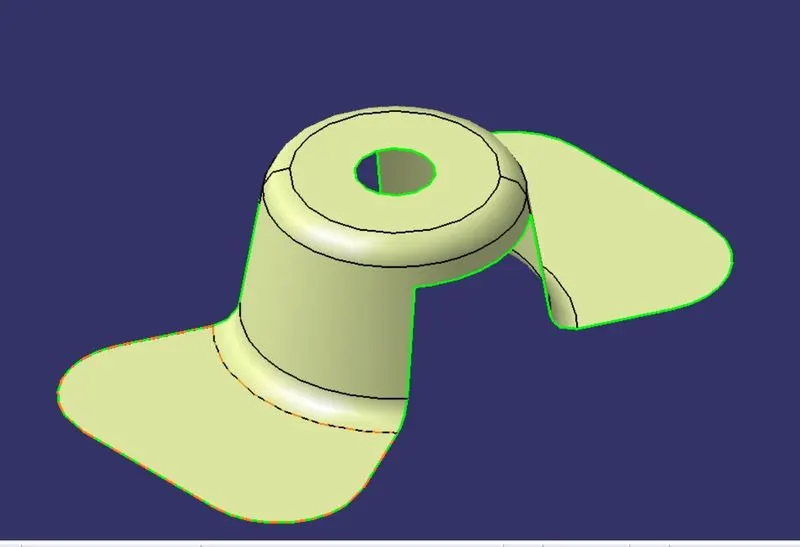
Week 8 - Challenge 1 - Draft Analysis on a Fan Cover
DRAFT ANALYSIS ON A FAN COVER:
Objection: Main objection is to perform draft analysis to check if the part has the given draft in its alll face and to determine the tooling axis.
Draft: it is a tool used in CATIA to make the face taper with respect to tooling axis. Tooling is thee direction of mold part ejection
Why Draft is Necessary:
However they are a required feature. A functional part for injection molding has to have drafts facing both cavity and core sides to reduce the risk of damage to the parts and ensure ejection. As the molten plastic flows into the closed die and fills the cavity, the material shrinks inside the mold upon cooling and as a result grips the core.Without any taper, the part would come out scratched while increasing wear and tear on the mold and shortening the tool life. Even worse - if the part does not eject, it requires a production halt to manually peel it off.What’s also important is to overcome the vacuum forces by letting air in between the metal and the plastic for the part to release properly. Adding an adequate draft angle ensures that warpage upon ejection is prevented while maintaining a decent cosmetic finish.
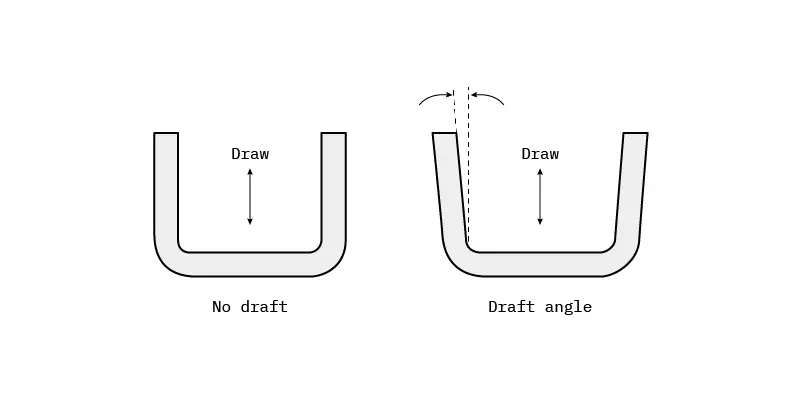
Draft angle Recommendasion:
1. 3 dgre is nominal draft.
2. 0.5 is minimum draft which increses cost of manifaturinng.
3. 7 degree for textured faces.
Steps involved in draft analysis
Step 1:
Merging of Class A surface. All Surfface should be connected no gap should be there we can check it using join command or boundry command if there is gap then green color line will apprear. So we have to make sure the sarface is joined.
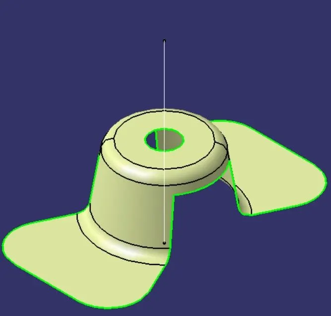
Step 2:
Now we analysis the best tooling direction using the X/Y/Z plane.
Step 3:
nnow we creat tooling clrearing along X/Y direction using the intersection of the plane with the class A
WE creat a refence plane.
by followinw similar method we make tooling direction in x.
X DIRECTION TOOLING AXIS:
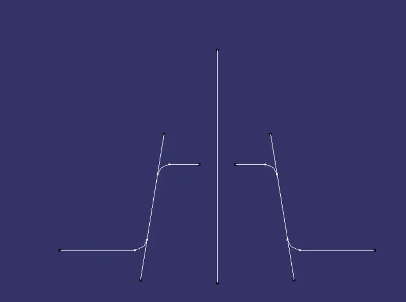
Y DIRECTION TOOLING AXIS:
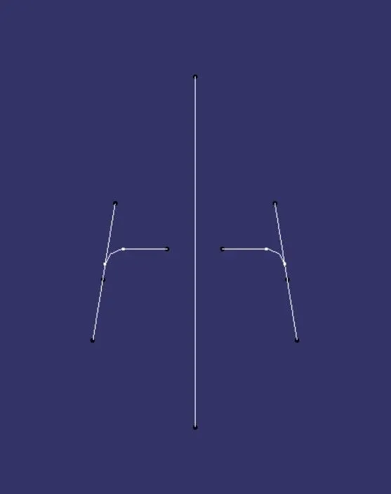
Bisection line concept:
With help of reference lines we make bisecting line. which is on the same plane as the refrence line but are line in normel direction. they are the either vertical or horizontal line at the point at the point of intersection of refrence line.
Making tooling direction line when we get the tooling direction in both X and Y direction then we use biesction line to gernerate the tooling axis.
Step 4:
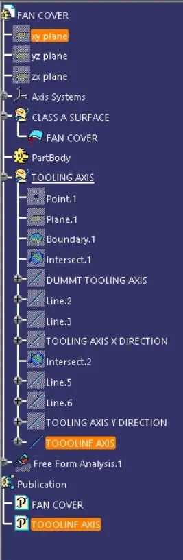
Publish the tooling line and the Class A Surface.
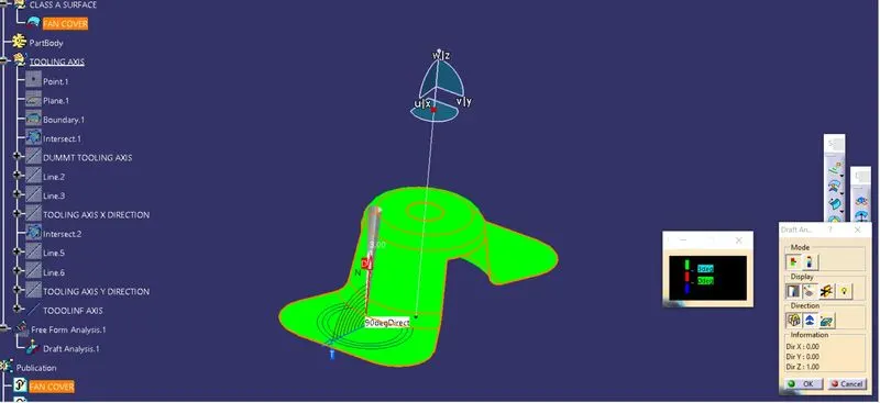
Draft Analysis:
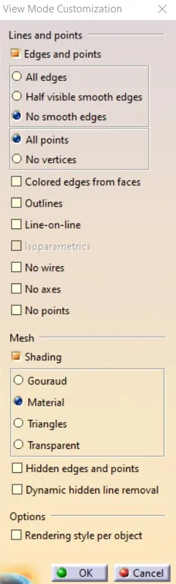
we change the view paprameter into customise mode with matrial checked.
Check wether the draft angele is more then 3 dgree
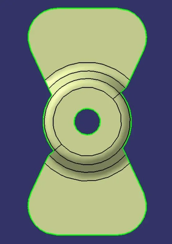
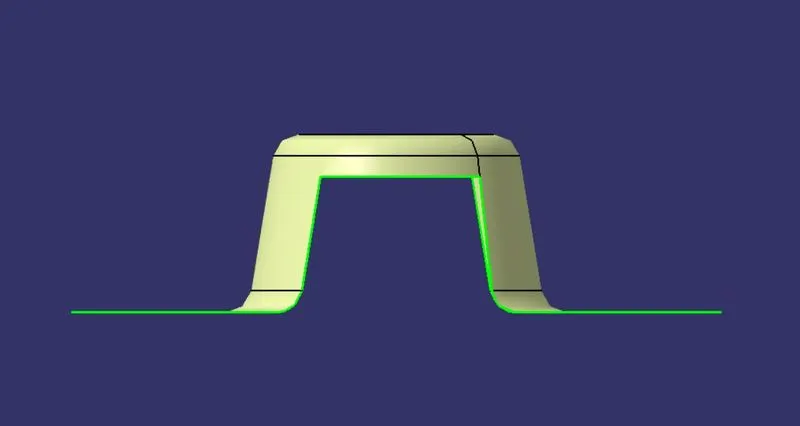
FAN COVER VIEWS
TOP VIEW:
SIDE VIEW:
ISOMETRIC VIEW: