Week 8 - Challenge 1 - Draft Analysis on a Fan Cover
Draft Analysis on a Fan Cover:
THEORIES OF DRAFT ANALYSIS:
Draft is required on all parts in the direction of mold movement in order to allow parts ti release or eject from the mold properly.
Draft is the angle in which the part is tapered to allow it to realese. As the part cools, it tends to want to shrink to the core side of the mold.
Adding draft helps the part to release. Most parts or application require a minimum of 1/2 to 1 degree, however 3 degrees is widely accepted as the norm.
Draft Analysis Report:
Steps to follow or Approach for the Analysis:
First ensure the class-A surface is properly joined and has no discontinuity on it. To identity it we use Boundary command or Join command.

Analyze the part manually to choose which direction is suitable for tooling axis. Whether it is toolable part or not.
1. From the below image can clearly see the hole which will be used for tooling axis. Because in this model X direction and Y direction are not possible to for put an tooling hole. So, We choose Z direction.
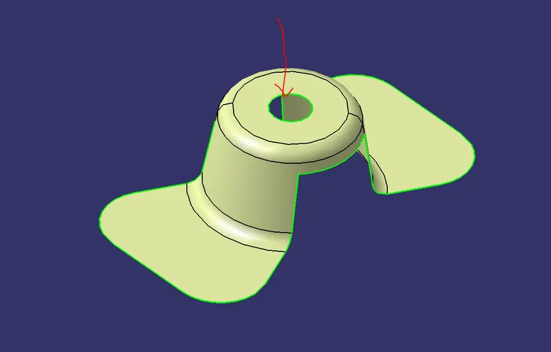
2. From X direction, it will be difficult for tooling the hole and Similarly from the Y direction the hole cannot be seen. So We finalize the decision that the Z direction is the only way for tooling hole for this model.
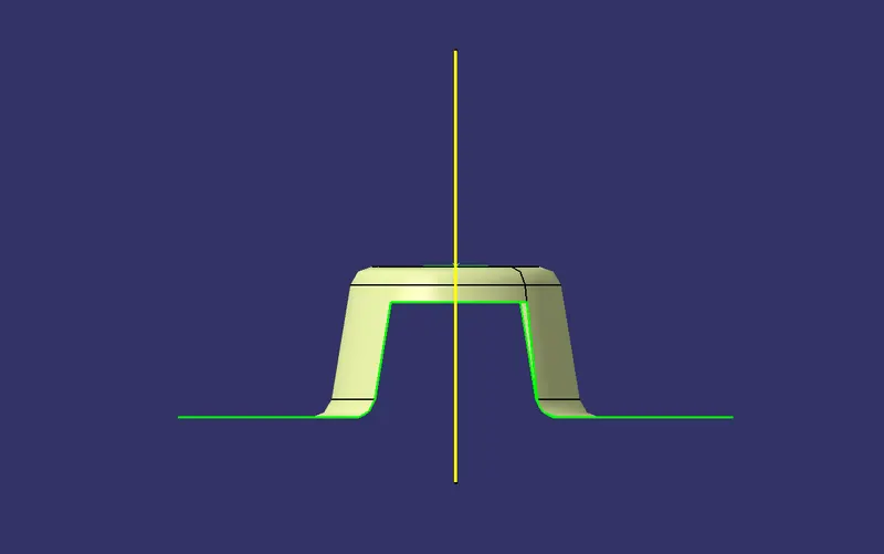
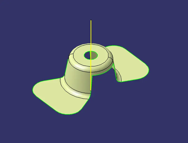
FIG 1 : DUMMY TOOLING AXIS.
Now we will use an axis to extract the surface. We use intersection Tool to get the Output for Tooling X direction.
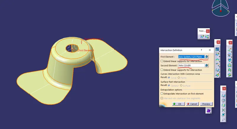
Make an axis system and intersect the ZX plane with the class-A surface. So that we will see which side or line will create problems or will be difficuit to be tooled.
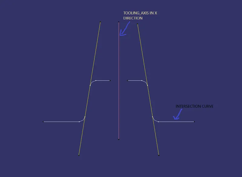
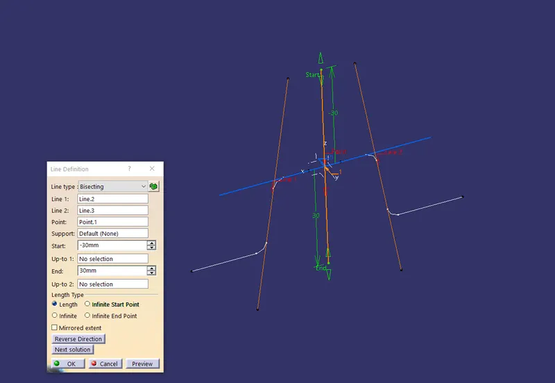
From the Above image we can see the intersection curve. Using the curve we can make a line along that surface using point to point option in Line command. Here we can see in the picture that we have made two lines(YELLOW LINES), now we will bisect the lines and choose the proper direction which we want, From the below picture we will get the bisected line and the result is TOOLING AXIS FOR X DIRECTION.
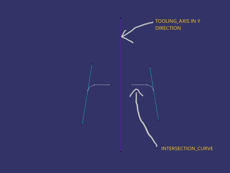
2. Similarly Intersect the YZ plane of the axis system with the class - A surface and repeat the same procedure again to get TOOLING AXIS FOR Y DIRECTION.
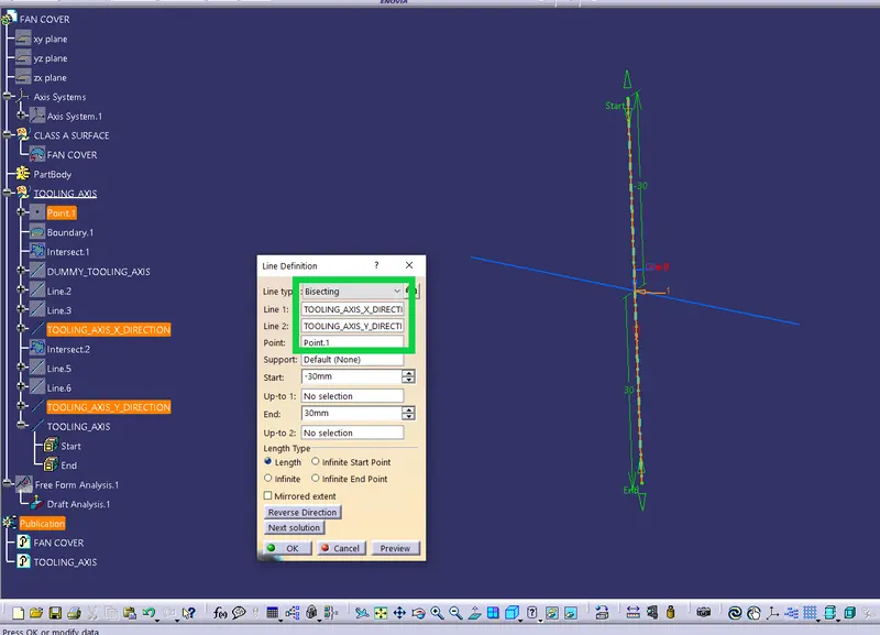
3. Now we have two axis in X and Y direction. Bisect these two axis to get the final Tooling axis.
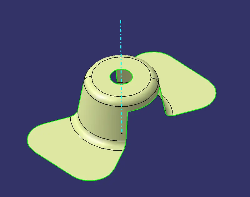
Now, the draft analysis have to be perform for the above model. Whether to identify all the surface are clearing the miinimum draft angle.
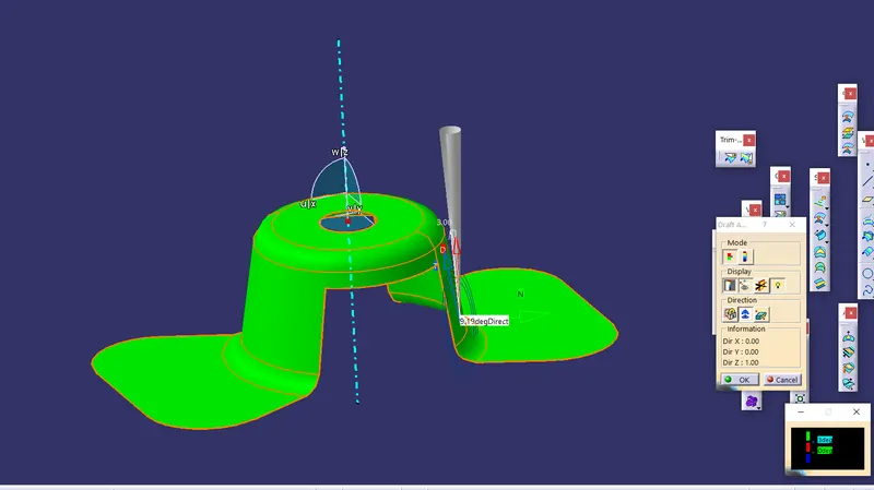
Click on the compass icon and align it with the tooling axis and click on the surface, we will get our results.
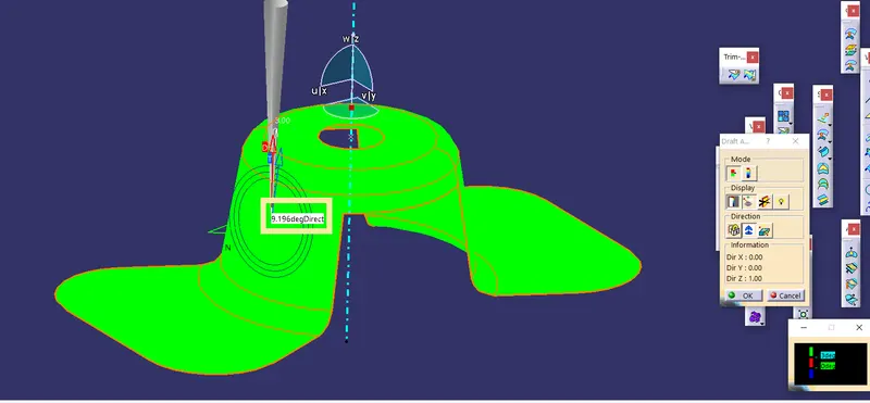
we will see different angles at each face or surface. We need to ensure all the surface are manufacturable or not.
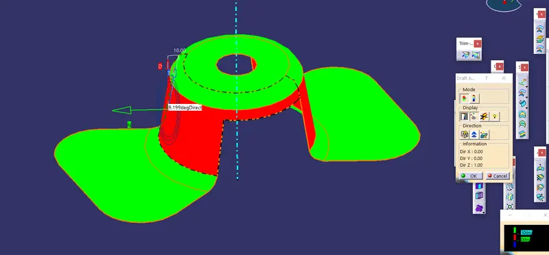
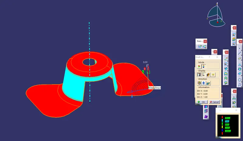
In here we use full analysis mode option. In that dialogue box we use different angle so that we get the result of differnt colors. this is how draft analysis will work. if we change our miminum angle and surface has diffrent angle we may get a result as we see in above Fig.
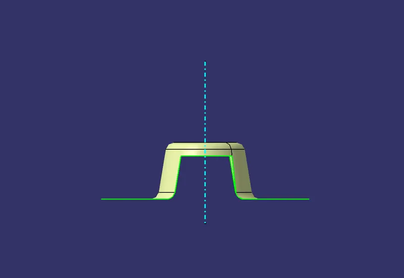
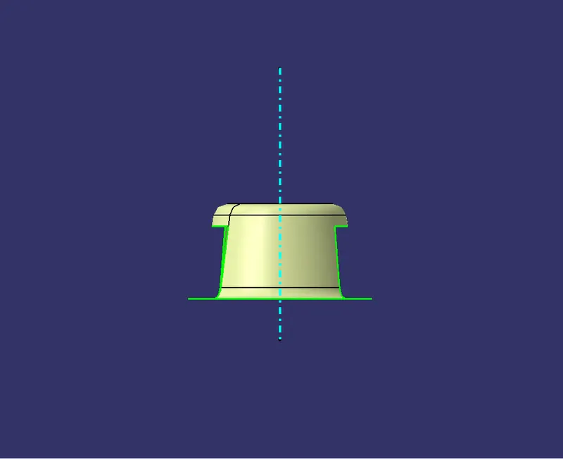

FIG : DIFFERENT ORTHO VIEWS
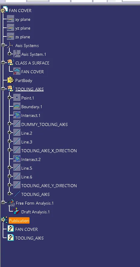
FIG : STRUCTURE TREE

FIG : PUBLICATION OF FAN COVER AND TOOLING AXIS.
CONCLUSION:
Thus the above challenge has been finished with the proper input and all the required documents are attached.