Week 8 - Challenge 1 - Draft Analysis on a Fan Cover
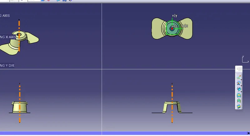
AIM- To Create the tooling axis for the given Fan cover model meeting the requirements of the draft angle and perform the Draft analysis on the model.
DRAFT
draft is the amount of taper for molded or cast parts perpendicular to the parting line. It can be measured in degrees or mm/mm (in/in).
Draft” just means tilting a part’s walls one way or the other–usually outward. A perfectly vertical 90deg wall is called “zero degree” draft. If the wall is tilted one way or the other, the draft is measured in degrees-from-vertica
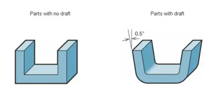
DRAFT ANGLE
A draft angle is a slant that is applied to each side of most features of an injection molded part. The angle, which is positioned to run toward the direction of a mold's pull and parting line, helps with releasing the part from the mold. It is rare that a component of a part does not need to be drafted
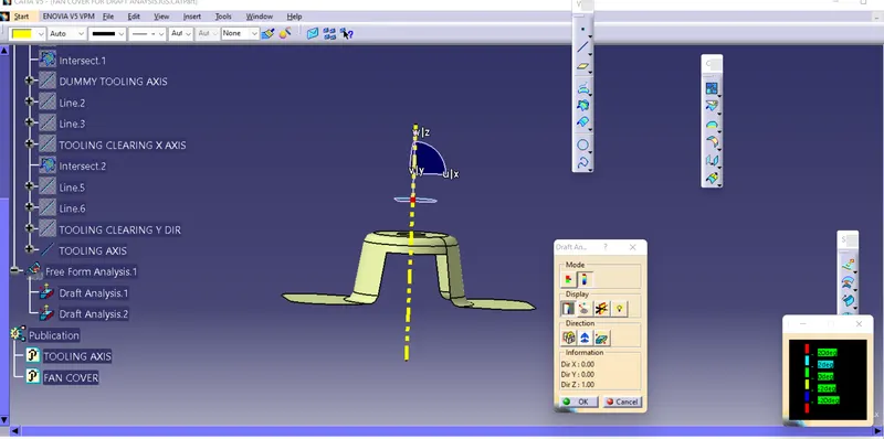
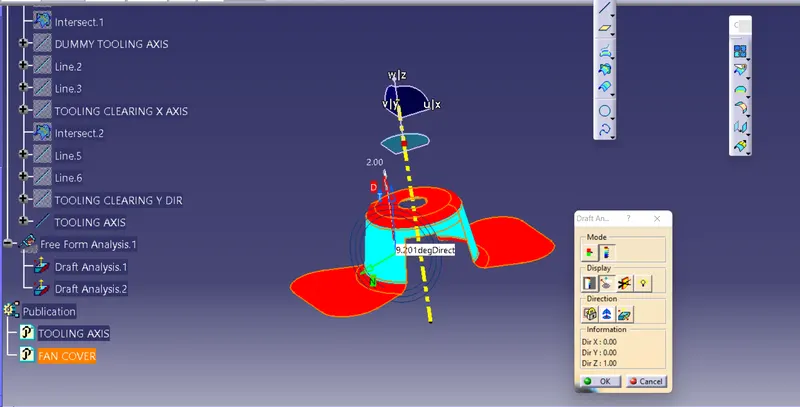
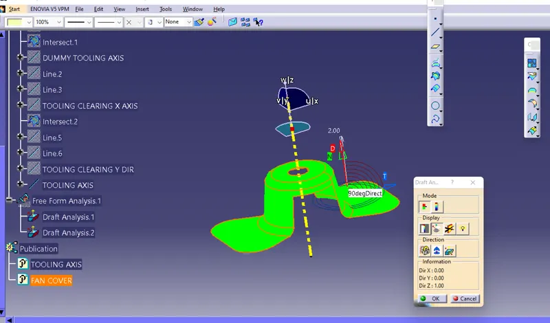
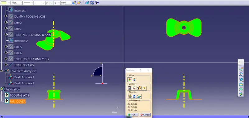
The draft analysis can be done in Catia V5 with respect to the tooling direction. The different color schemes are used to indicate the type of draft for instance green indicates positive draft, red indicates zero draft and blue indicates negative draft.
TREE STRUCTURE
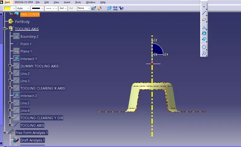
STEPS OF DRAFT ANGLE
STEP-1
CHECK the gaps of class A surface its done by join command.
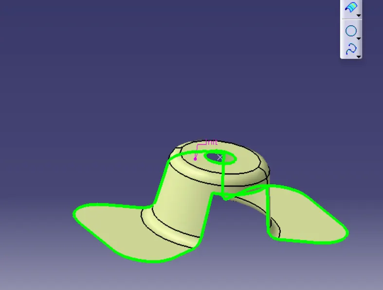
step 2
analyze the direction(x,y,z) in tooling direction.tooling direction must be choosen in direction part easly ejected in direction.this is called dummy tooling direction.
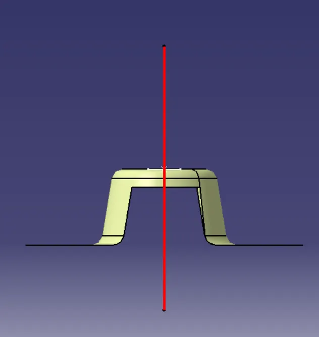
step-3
to find the tooling direction in x axis
bisecting the two line in a point.
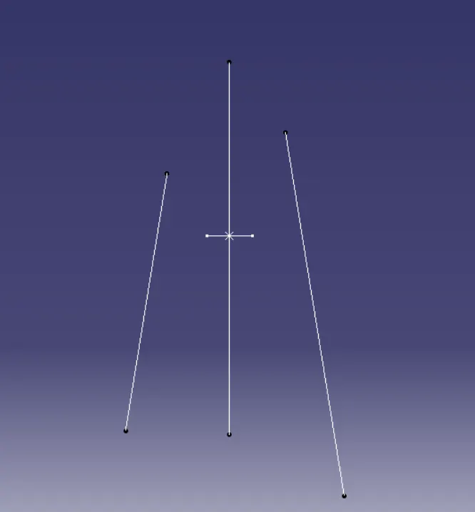
step 4
to find the axis of y tooling axis ..
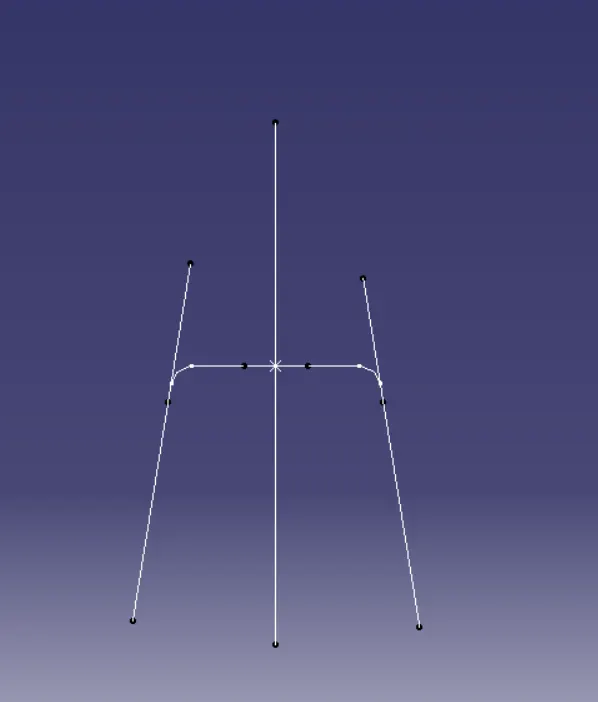
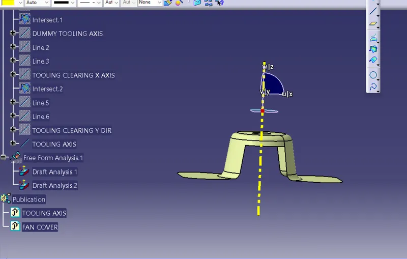
DRAFT ANALYSIS 1
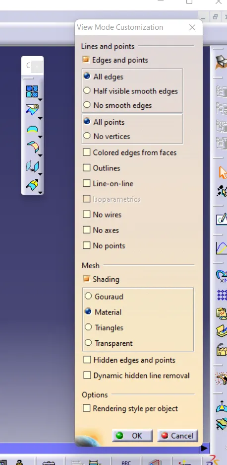
Conclusion
Thus the tooling axis for the given Fan cover model meeting the requirements of the draft angle is created and the Draft analysis on the model is performed.