Week 8 - Challenge 1 - Draft Analysis on a Fan Cover
OBJECTIVE:
The main of this project is to perform the draft analysis for the given fan cover and check for the different draft angles that are permitted for the following part Theory:
Draft:
A draft angle is a slant that is applied to each side of most features of an injection molded part. In other words Draft is providing tapers on the product features such as walls ribs posts and bosses that lie parallel to the direction of the release from the mold part ejection
The nominal draft is 3mm for plastic components and for automotive sheet metal components is 7mm
Why Draft is important?
Having easier ejection from the mold may seem like a minor concern, but the draft is crucial to manufacturing parts that meet your quality standard. Without draft, major problems can arise in the injection molding process that increases the time and cost of production When no draft is designed into the part, problems can come from friction and vacuums. These issues can damage both your part and even your mold in extreme cases.
We know that plastic shrinks as it cools, portions of the part may pull away from the mold while others grip the core. If there is no draft angle that allows a simple push from the ejector pins to pop the part out of the mold, the part’s surfaces will often drag along the mold as it is being ejected. This friction between the two surfaces can cause scratches or gouges in your part and affect the appearance Thus providing the draft reduces the above-mentioned issues, easy ejection, and lowers the cost of Production.
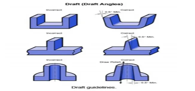
Draft recommendations:
While there is no exact thumb rule for the ideal draft some basic values to be followed are
- 3 degrees is Nominal Draft
- 5 degree can be manufactured at ribs
- 7 degree for the textured faces
DRAFT ANALYSIS:
Tooling axis: It is defined as the direction in which the molds opens or core and cavity
Pulling Direction: It corresponds to the reference from which the draft faces are defined (either in any direction) parting element: This plane or surface, face cuts the part into two and each portion is drafted according to the previously defined direction
Neutral element: This is obtained by bisecting the parting elements or even a single parting element is considered as neutral element, the entire drafted face will lie on this element
STEP 01:
Connectivity of Class A surface:
- The first and foremost thing to do is to check for the connectivity of the surfaces this is to ensure that there are no gaps between the surfaces if gaps are present then it should be resolved.
- This can be done visually or by creating boundaries, if their gaps are present they are graphically represented by green lines. If not while performing boundary command it shoes an error.
STEP 02 :
Creation of Dummy axis:
This is a normal line which we construct by analyzing the best possible direction(X/Y/Z axis) for the draft for the part, this axis is only for reference and is not used for Tooling Axis.
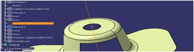
Creation of Tooling Axis:
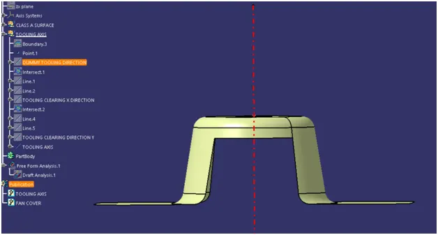
- Taking the dummy axis as a reference, intersect the class A surface along the different axis (XY/YZ/ZX ) Check for the possible places where the part might face difficulties while ejecting the component from the mold.
- Lines are drawn at the places where the part boundary has difficulties
- Later the Tooling axis in one direction (let’s say X) is obtained by bisecting the lines drawn in the above process
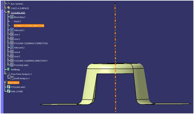
In the same way, the other axis is also checked and then the Tooling axis in another direction(let’s say Y) is drawn
Now both Tooling axes are bisected and the final Tooling direction is obtained which is further used for all draft analysis axis and later unto developing Class C and Class B surfaces
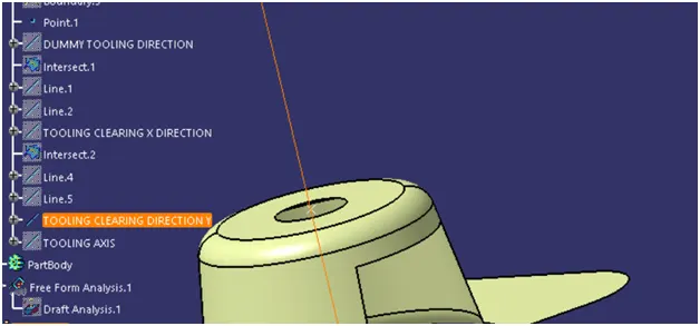
STEP 03
Publication:
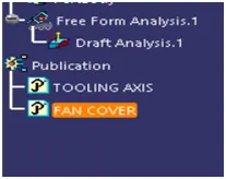
The publication is used for easy access to published components. These will come handy while modelling(we are not required to search the entire tree structure for a particular operation)
STEP 04
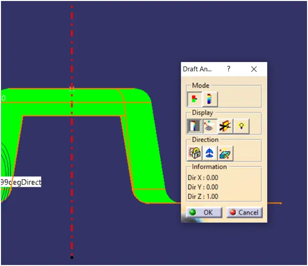
- Click the Inset—Analysis -- (Feature) Draft Analysis icon
- If material is not on There will be a warning message is shown and then we need to select the material The Draft Analysis dialog box is displayed.
- It gives information on the display (color scale), the draft direction, and the direction values
DISPLAY OPTION:
- Activate the On the fly checkbox and move the pointer over the surface. This option enables you to perform local analysis.
- Arrows are displayed under the pointer, identifying the normal to the surface at the pointer location (green arrow), the draft direction (red arrow), and the tangent (blue arrow).
- As you move the pointer over the surface, the display is dynamically updated. Furthermore, circles are displayed indicating the plane tangent to the surface at this point.
- Click the No Highlight Representations button to set the display option of highlight effect sources as "on/off". When checked "On" the surfaces are selected but they will not be seen in the specification tree.
- Click the Light Effect button and the colors of the analyzed elements react to the light source
- Click the Inverse button to automatically reverse the draft direction
- Click the Locked direction icon By default the analysis is locked, meaning it is done according to a specified direction: the compass w axis. In P1 mode, the default analysis direction is the general document axis system's z-axis.
- Click the Compass icon to define the new current draft direction.
- The compass lets you define the pulling direction that will be used from removing the part.
- Once you have finished analyzing the surface, click OK in the Draft Analysis dialog box.
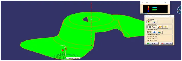
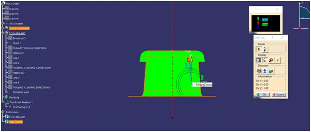
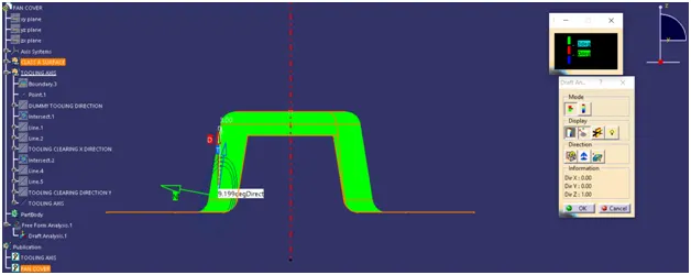
DRAFT ANALYSIS COLORS(for this model ):
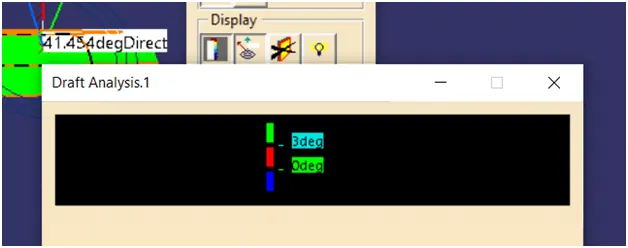
Red - (Draft is not possible)
Green -(Draft within range)
Blue - (Draft in limits)