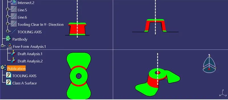
Week 8 - Challenge 1 - Draft Analysis on a Fan Cover
Draft Analysis on a Fan Cover
OBJECTIVEVE :-
To Draft Analysis on fan cover using Catia V5 Software with suitable Tooling Axis
What is the Draft ?
Drafts are defined on molded parts to make them easier to remove from molds.
There are two ways of determining the objects to draft: either by explicitly selecting the object or by selecting the neutral element, which makes the application detect the appropriate faces to use.
Major Industries use the minimm Draft angle is 3 degrees.
PROCESS OF DRAFT ANALYSIS -
First we check the continuity of the given Class -A Surface.
Check the Tree Directions (X, Y, Z – axis) and Finally we Decided which is the Best possible Direction to Produce a Mold. That direction of axis is Called Dummy tolling Axis.
A Fan with several drafted surfaces that is oriented in part location. That the Draft Analysis initially Assumes a Z-axis Direction.
At Z-axis Drection The Faces are eaither Positive or Negative Draft So the Z- Axis We taken as Dummy tooling Axis.we need to create a prfect Tooing Axis.
PROCESS OF TOOLING AXIS CREATION -
What is the Tooling Axis ?
Tooling Axis means Direction In which The Mold opens Or Core and Cavity Opens.
Create a Axis system On a Point
Create intersecting line on the ZX- plane and Class -A surface,
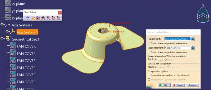
Further produces the lines by using Surface points,
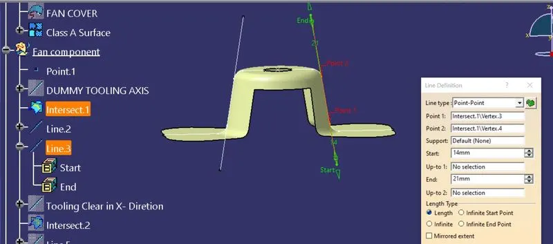
Finally Create the Bisecting line that is called as the Tooling clear in X- Direction.
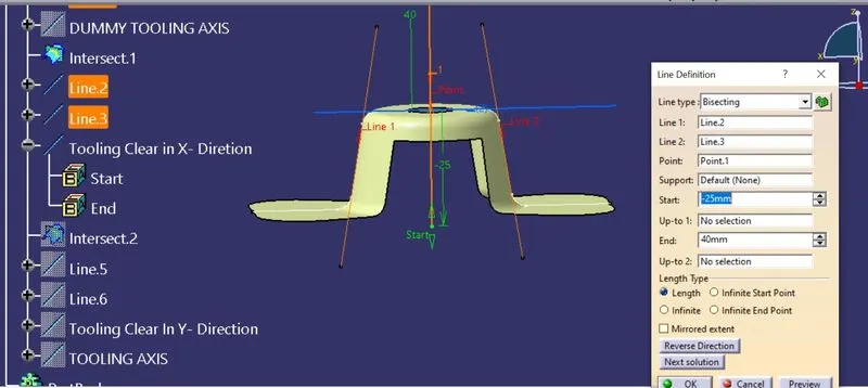
Again we create the Same process on YZ -plane and Class -A surface, further produces the lines by using Surface points, Finally Create the Bisecting line that has the Tooling clear in Y- Direction.
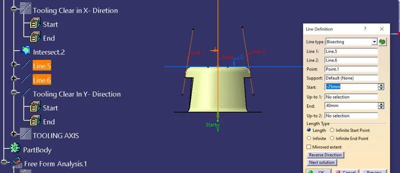
Finally create the bisector line with Tooling clear in X- Direction and Tooling clear in Y- Direction.That Bisector line is Called as the Tooling axis.
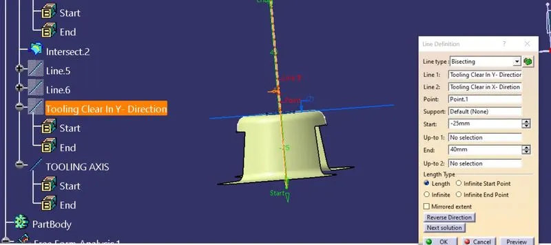
PROCESS OF DRAFT ANALYSIS –
The first step is to change your shading style to “shading with Material”
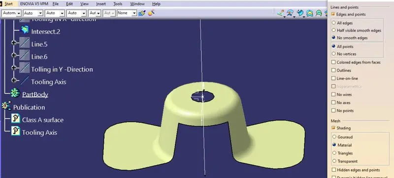
Go for draft analysis (INSERT - ANALYSIS - FEATURE DRAFT ANALYSIS )
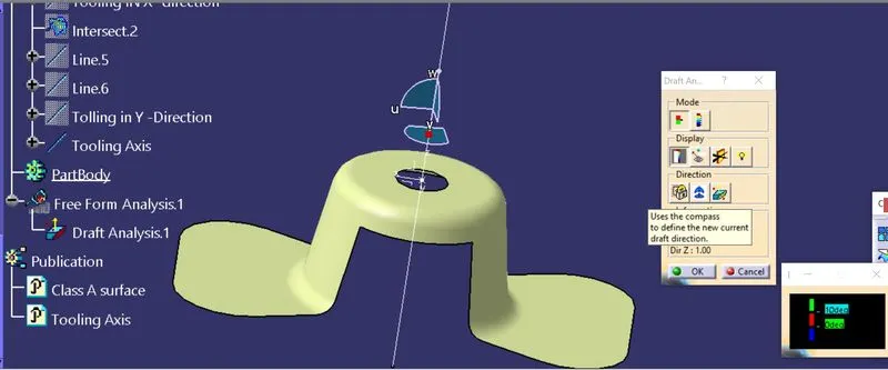
This can be done with the dragging of the compass with respect to Tooling axis.
Dragging Method -Begin clicking on the compass direction icon within the draft analysis dialogue box. This will be snap the compass onto the Tooling axis.
 NpNoe
NpNoe
.Now switch on the Quick Analysis Mode, Running the Running Point On Different surfaces And Find the Draft Angles
We consider the Majorly Industrys Using Draft angle -3 Degree
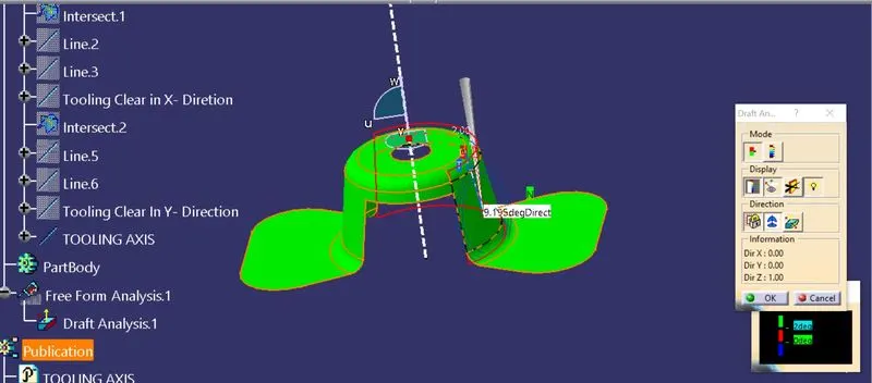
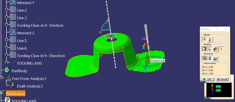
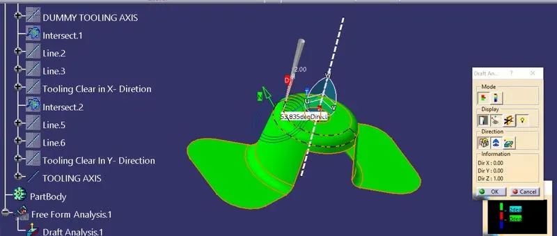
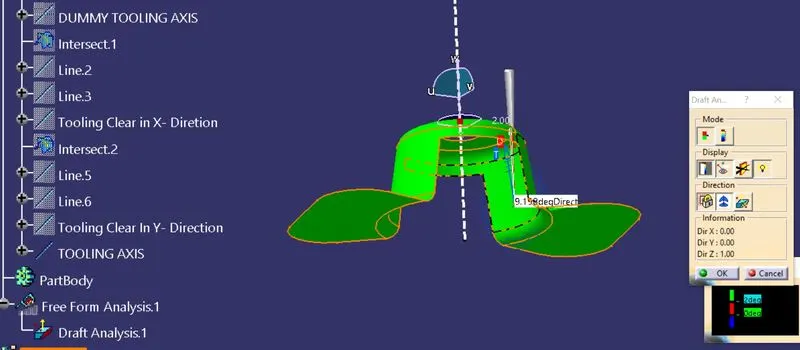
If Maintain Minimum Draft Angle 10 Degrees
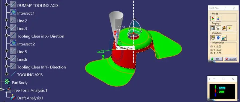
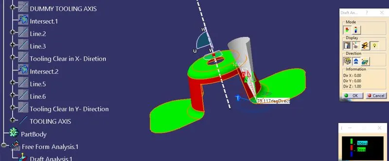
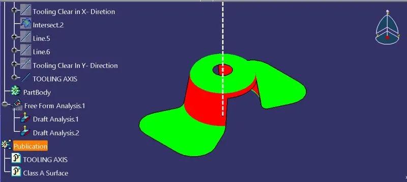
Tree Structure
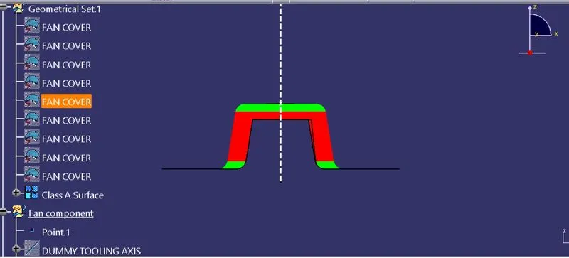
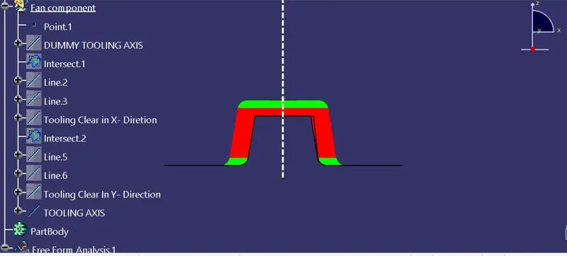
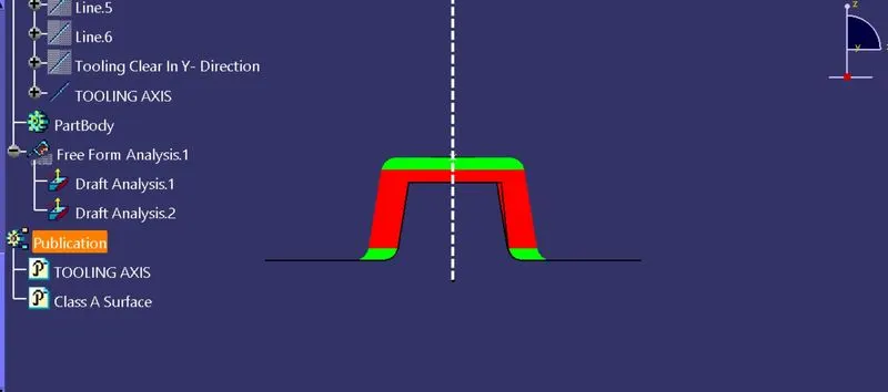
3 D views
Front view
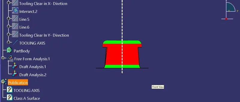
Side View
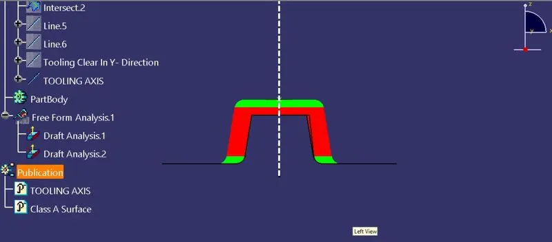
Top view
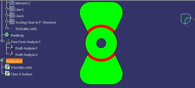
ISOMETRIC VIEW
MULTI VIEW