FINAL INDEPENDENT PROJECT
Modified Road master pickup combination of solar
Objective
This is the final independent project report on Ultimate solid works course about ideation, Design and modelling of Solar Electrical Road Master pickup in Solid works.
The main Aim of the project is understand various challenges in creating and how to represent as final working model through various design features in Solid works.
Ideation
To Reduce the transportation cost at light loads over short distances, These vehicle use for intracity low tonnage cargo delivery, like Postal and courier services or Home delivery of Appliances from dealer to customer.
Geometric Dimension
The Project is modeled using conceptual dimensions with using Road Master pickup Blue print and Rough Dimensions where obtained from the Solar Electrical Road Master pickup Model And the parts to be modeled are Sketched based on suitable Dimensions.
Part modeling
This is the second phase of the project .From ideation images a concept Sketch is developed and the parts modeled for Solar Electric Road master pickup is derived. The parts were developed feature based modeling and surface through a direct and initiative graphical manipulation. The parts to be modeled are given below the table.
|
PARTS |
No of parts |
|
Chassis |
1 |
|
Front Axle |
1 |
|
Rear Axle |
1 |
|
Break Drum |
2 |
|
Body |
1 |
|
Front Hood |
1 |
|
Right side Door |
1 |
|
Left Side Door |
1 |
|
Back Door |
1 |
|
Rack and Pinion Mechanism |
1 |
|
Steering |
1 |
|
Sheet |
2 |
|
Wheel |
4 |
|
Battery |
2 |
|
Front Bumper |
1 |
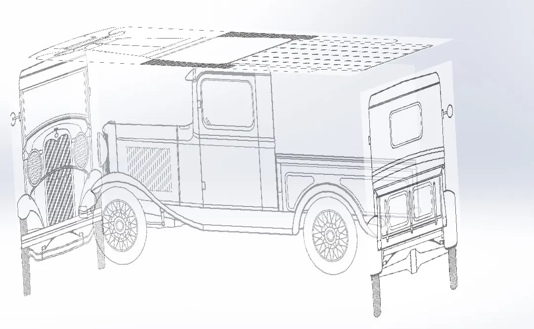
BLUE PRINT
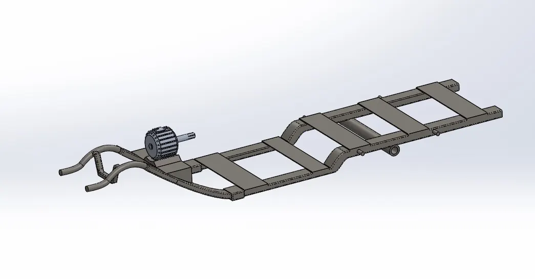
Chassis
Chassis forms the bae of the model and also supporting frame for mounting various parts of the vehicle
It has three main parts
Synchronous Motor
Wheel mounting Frame
Overhanging Front Frame
Features involved
Sketch
Boss Extrude
Sweep
Mirror feature
Fillet
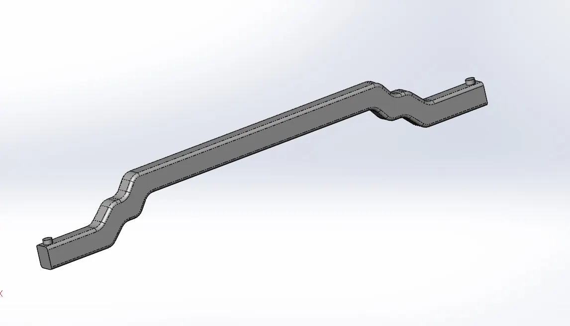
Front Axle
It is support the Break drum and Rack and pinion Gear, its carries the weight of the front part, front axle are dead axle.
Features involved
Boss Extrude
Fillet
Mirror Feature
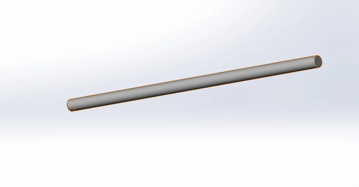
REAR AXLE
Rear axle use to carry the weight of the vehicle as well as to facilitate to transmit the drive to rear wheels, generally rear axle drives power obtained from the differential is transmitted to the rear wheels through the rear axle.
Features involved
Boss Extrude
BREAK DRUM
Break drum mounted on front Axle and it support the wheels
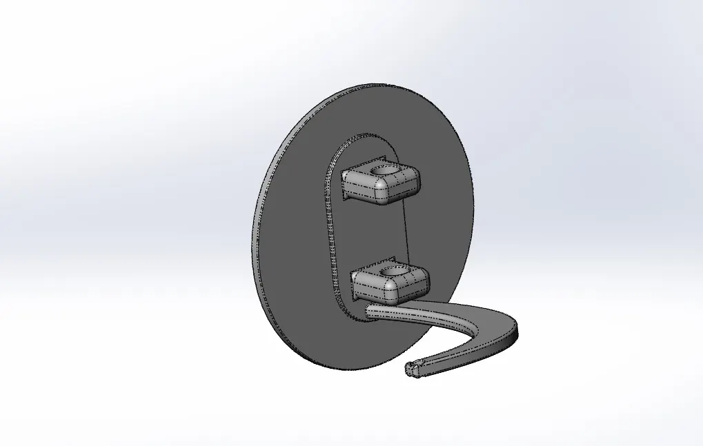
Features involved
Boss extrude
Cut extrude
Fillet
BODY
Body is the closed section of all the parts, with a platform body on which good are carried.
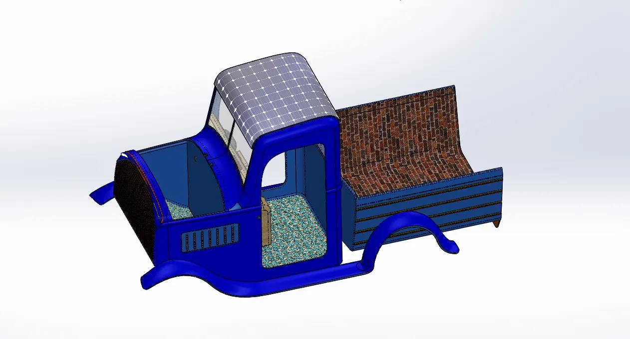
Features involved
Projected curve
Surface loft
Surface Extrude
Ruled Surface
Surface Trim
Knit
Shell
Split
Split Line
Offset Surface
Fillet
Chamfer
Dome
FRONT HOOD
Hood also referred to as a Bonnet, is the hinged cover that rests over the engine of a front engine vehicle. Its purpose is to provide access to the engine for repair and maintenance.
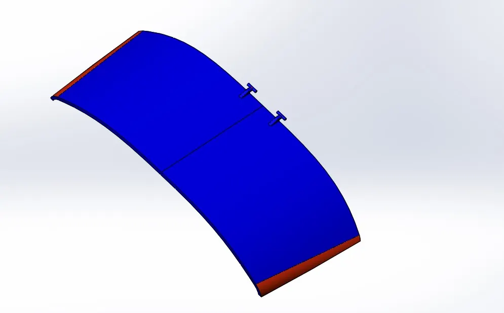
Features involved
Boss Extrude
Fillet
RIGHT SIDE DOOR
A pick up Right side door attached by hinged, in front of an opening which is used for driver entering and exiting a vehicle, A vehicle door can be opened to provide access to the opening, or closed to secure it.
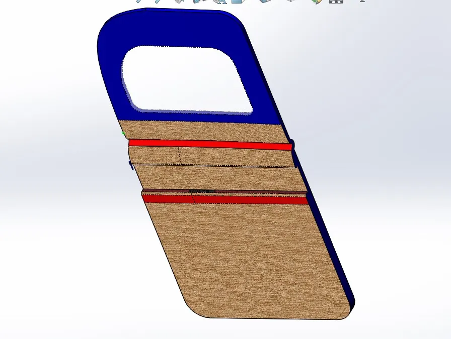
Features involved
Boss Extrude
Cut Extrude
Fillet
Split line
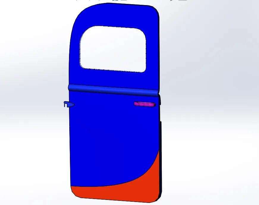
LEFT SIDE DOOR
Door is attached by hinged, it is used to entering and exiting the passenger in a vehicle.
Features involved
Boss Extrude
Cut Extrude
Fillet
Split line
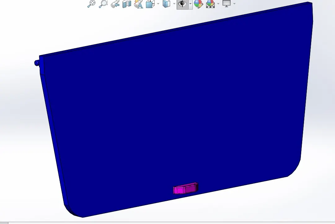
BACK DOOR
Back door is used for Entering and exiting load from vehicle.
Features involved
Boss Extrude
Cut Extrude
Fillet
Mirror
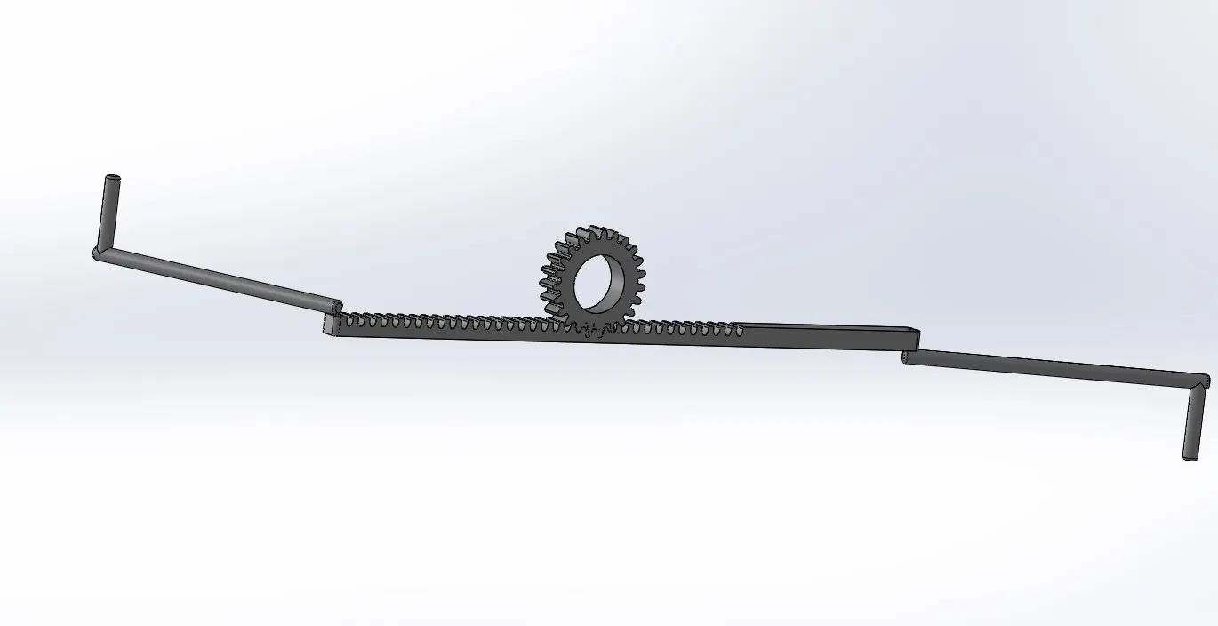
RACK AND PINION GEAR
Rack and pinion Gears are used to convert rotation into linear motion. The steering wheel rotates a gear which engages the rack, as gear turns, it slide the rack either to right or left, depending on which why turn the wheel.
Features involved
Boss Extrude
Cut Extrude
Fillet
Mirror
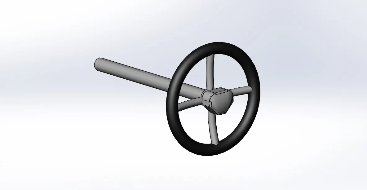
STEERIG WHEEL
The Steering wheel used to control the Steering System and direction of the vehicle and comprises a linkage system to direct the vehicle, Through the front Wheel.
Features involved
Solid Sweep
Boss Extrude
Dome
Fillet
WHEEL
Wheel has contain Two parts
Rim
Tyre
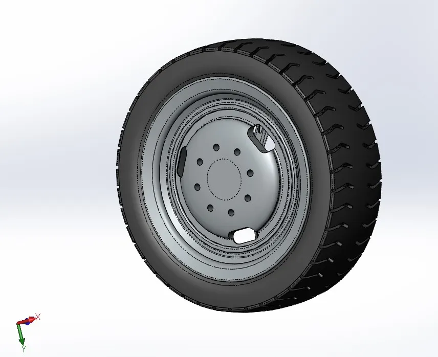
Features involved
Revolve
Revolve Cut
Cut extrude
Fillet
Chamfer
SEAT
Seat is used for carrying a rider and, possibly a passenger, and which is attached behind the driver seat.
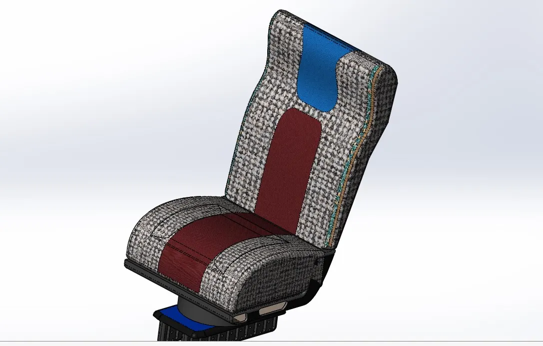
Features involved
Boss Extrude
Cut Extrude
Fillet
Split line
Front Bumper
The Purpose of bumper is to reduce or prevent physical damage to the front of vehicle in low speed crashes.
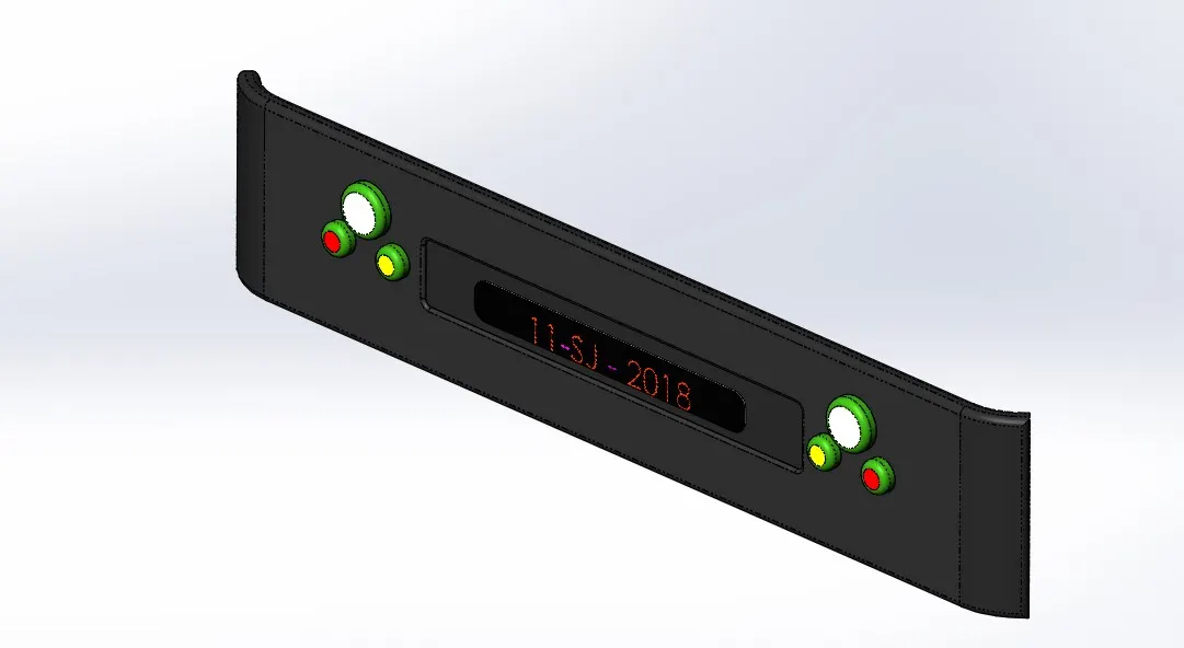
Features involved
Boss Extrude
Mirror
Fillet
Cut Extrude
Dome
BATTERY
The battery is the source for the prime mover and the lithium ion cells are chosen as a battery source. The cell re arranged in series. This allows easy replacement and maintenance.
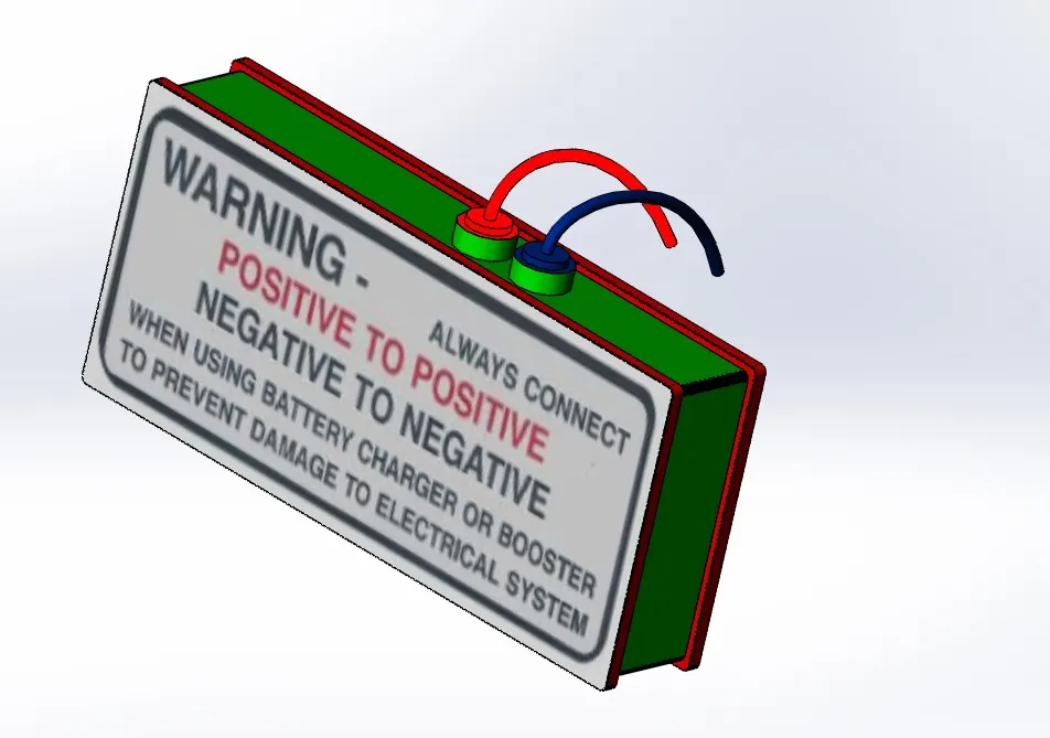
Features involved
Boss Extrude
Projected Curve
Sold Sweep
Fiilet
ASSEMBLY
The parts are designed are assembled through a bottom top approach. As said chassis forms the base and fixed to the Assembly. All other parts are mounted using appropriate mating conditions.
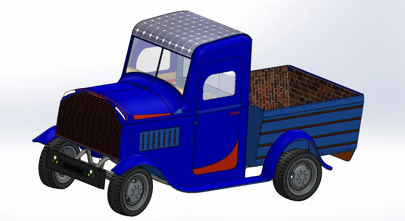
PROCEDURE
- The chassis inserted to Assembly model is fixed.
- The front Axle Are inserted along suitable axis and fixed using parallel, coincidence and distance mates
- Break Drum and Rack and pinion mechanism fixed to the Axle.
- Rear axle are also inserted along axis using coincidence and concentric mates.
- The Four wheels Are inserted and rotated Along suitable axis and fixed using coincidence and concentric mate
- Then Body is mounted Above the chassis.
- Battery module mounted on the body
- The moving Parts of the assembly are hood ,right door, Left door, Back door, Rack and pinion ,wheels.
- Mates Involved
- Parallel mate
- Coincident mate
- Distance mate
- Concentric mate
- Limit Angle mate
- Rack and pinion Mate
RENDERING
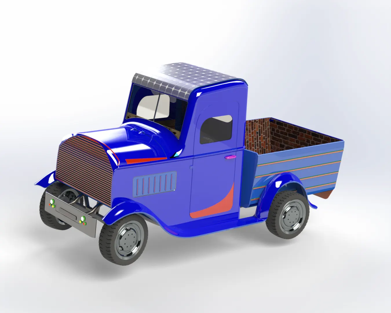
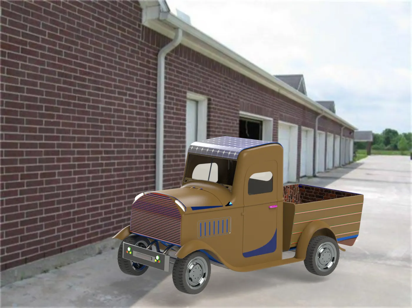
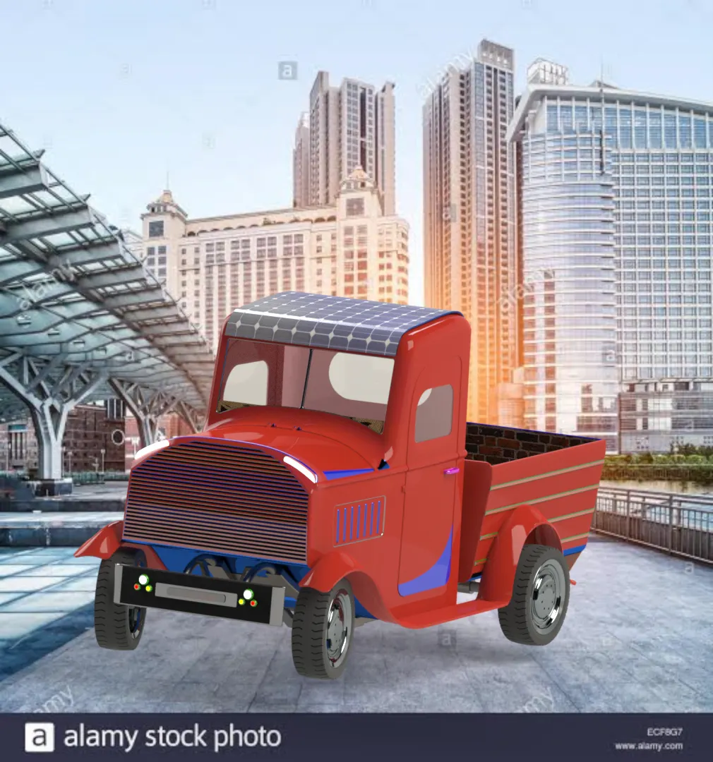
- Finally the model is rendered using good passes and maximum render quality.
- The images are shown below
-
-
-
CONCLUSION
- Thus the complete solar is modelled and simulated using solid works, photo view 360 and solid work visualize. Thus the feature based modelling and simulation concepts were grasped thoroughly and modelling and simulation skills in solid works.
PROJECT SCOPE
- Thus the project can be used in future to use increase dimension by 1:5 ratio and also add additional motion to engine units and complete working model can be simulated by adding further more components (like bearings, springs, breaks steering mechanism…) and Gear system with differential unit.
REFERENCE
- Blue print -Decals –
- https://i.pinimg.com/564x/24/94/be/2494be1f664e255455fd0f6993de2842.jpg
- Ipinimg.com
- Battery
- https://www.google.com/url?sa=i&url=https%3A%2F%2Fwww.impactdecals.co.uk%2Fproducts%2Fporsche-914-battery-warning-decal&psig=AOvVaw2KEXAUIAwI8lyR4nnnp8Zn&ust=1596214550601000&source=images&cd=vfe&ved=2ahUKEwiEg7vbuPXqAhWFN3IKHV-DBfoQr4kDegUIARDBAQ
- https://www.google.com/url?sa=i&url=https%3A%2F%2Fwww.opgi.com%2Fdecals%2Fengine-compartment-decals%2Fbattery-warning-decals%2Fdecal-63-64-buick-battery-connection-warning-sdb0093.html&psig=AOvVaw0nNvwY3htms_xBdvjFHuYK&ust=1596246744105000&source=images&cd=vfe&ved=2ahUKEwjFzMLSsPbqAhXdlUsFHbDCARsQr4kDegUIARCRAg
- Steering –
- https://www.carsoda.com/products/bling-steering-wheel-logo-sticker-decal-for-nissan-juke-sedan-sentra-leaf-quest-gtr
- Speedo Meter-
- https://in.pinterest.com/pin/439171401133244884/
- graphicriver.com
- Rack and pinion gear –
https://youtu.be/wQuijDqJQTk
- Fuel indicator -
https://in.pinterest.com/pin/352828952059797907/
Etsy.com
- Solar panel -
- https://i.pinimg.com/564x/a0/a0/f7/a0a0f7bb67921d9004878ac623b05076.jpg